Wall Thinning in Tube Bending: Stretch, Geometry and Checks
Wall thinning in tube bending explained: why the outside wall stretches, a simple geometry estimate, how to check real thinning, and how to limit it.

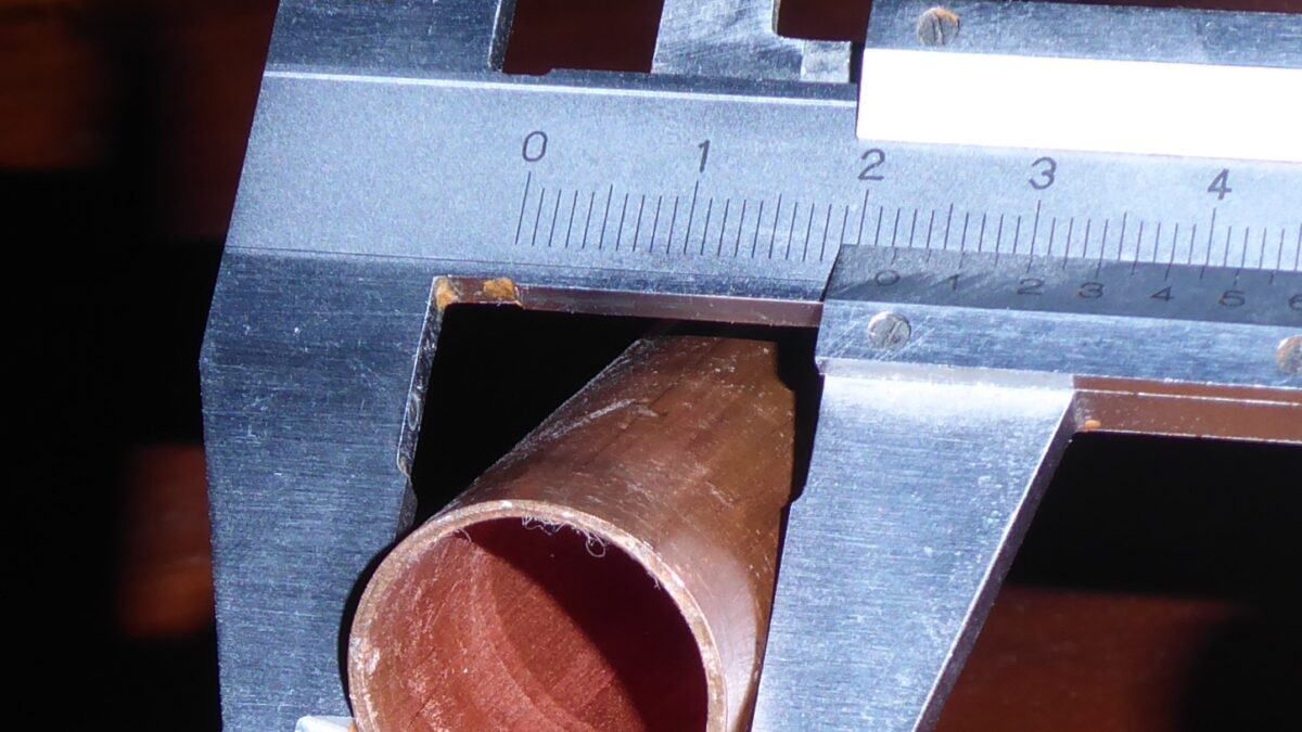
Bend a tube and you change more than its direction. The outside of the bend gets stretched, and stretched metal gets thinner. The inside gets squeezed, and squeezed metal gets thicker. That’s wall thinning in tube bending, and it happens on every bend you make, whether you can see it or not.
For most garage parts it’s no big deal. But on tight bends, thin wall, pressure lines and safety parts like cages, it’s worth understanding. The catch is that there’s no simple, proven formula that tells you exactly how thin the wall will get. Anyone who hands you one exact number for every tube is guessing.
What we can do is use simple geometry to see how hard the outside of the bend is being stretched. In this guide you’ll learn why thinning happens, how to estimate the stretch with one easy formula, how to check real thinning on a test piece, and how to keep it under control with smart die and tube choices.
Wall thinning is the outside wall of a bend getting thinner as it stretches. The inside wall gets thicker as it’s squeezed.
- Geometry gives a quick stretch estimate: outer-fibre stretch ≈ OD ÷ (2 × CLR). For 1.75″ tube on a 6″ CLR, that’s about 14.6%.
- Stretch isn’t the same as thinning. No simple, validated formula predicts the final wall. Check it by sectioning a test bend or with an ultrasonic gauge.
- The biggest lever is the bend radius. A larger CLR means less stretch. Pick your die and bender with that in mind.
📋 In this guide
- What is wall thinning in tube bending?
- Why the outside wall gets thinner
- The geometry of outer-wall stretch
- Stretch at common bend radii
- Stretch is not the same as thinning
- Why wall thinning matters
- How to check wall thinning
- How to limit wall thinning
- Real-life lessons
- Common mistakes and fixes
- Pro tips
- FAQ
- Your wall-thinning checklist
What is wall thinning in tube bending?
Picture a tube bent into a 90° elbow. The outside of the elbow, called the extrados, travels a longer path than the inside, called the intrados. The tube’s centerline sits in between.
Metal can’t appear from nowhere. When the outer wall has to cover a longer path, it stretches. When metal stretches in one direction, it gets thinner in another. So the outer wall ends up thinner than it was. On the inside, the opposite happens. The metal is squeezed into a shorter path, so it thickens.
That’s all wall thinning means: the outside wall of a bend losing some thickness. You’ll also see it called outside wall thinning or outer wall stretch. Its partner on the inside is inner wall thickening.
A few key terms will make the rest of this guide easier:
- OD: the tube’s outside diameter.
- Wall: the wall thickness, like .120″.
- CLR: centerline radius, the radius of the bend measured to the tube’s center. It’s set by your die.
- D of bend: CLR ÷ OD. A 6″ CLR on 1.75″ tube is about 3.4D.
- Wall factor: OD ÷ wall. Bigger numbers mean thinner wall for the size.
If any of those are new, our centerline radius guide and our glossary explain them in plain English.
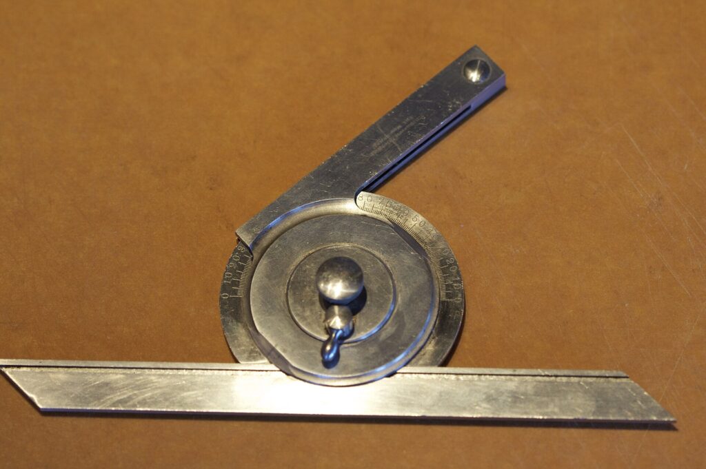
Why the outside wall gets thinner
Think of a rubber band. Stretch it and it gets longer and thinner. Steel isn’t rubber, but once you bend it past its elastic limit, it flows in a similar way. Its volume stays about the same, so a longer piece has to give up thickness or width somewhere.
In a tube bend, the stretch runs along the length of the tube on the outside of the bend. The wall there gets pulled thinner. The squeeze on the inside does the reverse and builds up thickness. Bender maker Rogue Fabrication describes it simply: the outside of the bend stretches, while the inside is in compression (Rogue Fab stainless guide).
Thinning travels with other defects
Thinning rarely shows up alone. The same forces cause other changes:
- Ovality: the stretched outer wall pulls in toward the center and the section flattens. See our ovality guide.
- Wrinkles: if the inner wall can’t take the squeeze, it buckles. Rogue Fab notes this happens when the wall is thin relative to the bend radius.
- Work hardening: some metals get harder where they stretch. Rogue Fab says austenitic stainless, like 304 and 316, work hardens quickly during bending.
The bend radius drives it
The tighter the bend, the bigger the difference between the outer and inner paths. That means more stretch outside, more squeeze inside, and more thinning. The next section shows how to put a number on that stretch with nothing but a calculator.
Every bend thins the outside wall a little. The question isn’t “is there thinning?” It’s “is there more than this part can accept?” That answer comes from your design, spec or rulebook.
The geometry of outer-wall stretch
Here’s the useful bit. You can estimate how much the outside of a bend stretches with simple circle geometry. No lab, no software.
The formula
The length of any arc is its radius times the bend angle (in radians). The centerline runs at the CLR. The outside surface runs at CLR + OD ÷ 2. So the outer surface is longer by a fraction of:
Outer-fibre stretch ≈ OD ÷ (2 × CLR)
The inside surface runs at CLR − OD ÷ 2, so it’s squeezed by the same fraction. Since D of bend is CLR ÷ OD, you can also write it as stretch ≈ 1 ÷ (2 × D). That makes it easy to compare dies at a glance.
Worked example: 1.75″ tube on a 6″ CLR
Let’s check it with real lengths for a 90° bend. A 90° bend is π ÷ 2, or about 1.5708 radians.
- Centerline arc: 6 × 1.5708 = 9.425″.
- Outer radius: 6 + (1.75 ÷ 2) = 6.875″. Outer arc: 6.875 × 1.5708 = 10.799″.
- Inner radius: 6 − 0.875 = 5.125″. Inner arc: 5.125 × 1.5708 = 8.050″.
- Outer stretch: 10.799 − 9.425 = 1.374″ longer. Then 1.374 ÷ 9.425 ≈ 14.6%.
- Shortcut check: 1.75 ÷ (2 × 6) = 1.75 ÷ 12 ≈ 0.146, or 14.6%. It matches.
The inside is 9.425 − 8.050 ≈ 1.37″ shorter, also about 14.6%. So the outside surface is stretched about 14.6% and the inside squeezed about 14.6%, measured against the centerline. We use the outside surface because it’s the worst case. The middle of the wall stretches a little less.
The angle doesn’t change the percentage
Try the same tube at 45°. The centerline arc is 4.71″ and the outer arc is 5.40″. The outside is still about 14.6% longer. In this simple model, the percentage stretch depends on OD and CLR, not on how far you bend. A bigger bend just stretches a longer stretch of tube by the same amount.
Want to see this on screen? Our geometry visualizer draws the inner, outer and centerline arcs. The bend calculator gives you D of bend and arc lengths for your die.
Wall thinning in tube bending: stretch at common bend radii
Because stretch ≈ 1 ÷ (2 × D), you can build a quick table. The D values below aren’t random. Each one ties back to a published source or a common die size.
| D of bend (CLR ÷ OD) | Outer stretch ≈ 1 ÷ (2D) | Where you see this radius |
|---|---|---|
| 1D | 50% | Tight mandrel exhaust bends (Vibrant sells 1D bends) |
| 1.5D | 33% | Common aftermarket mandrel exhaust bends |
| 2D | 25% | The Fabricator’s mandrel example: 2″ tube on a 4″ CLR |
| 3D | 16.7% | Pro-Tools’ practical minimum without a mandrel; SCCA Time Trials cage minimum |
| About 3.4D | 14.6% | 1.75″ tube on a 6″ CLR die |
| About 3.7D | 13.5% | 1.75″ tube on a 6.5″ CLR, a common off-road die per Baileigh |
| 4D | 12.5% | Baileigh’s suggested starting point |
Sources for the radius column: Vibrant Performance, The Fabricator, Pro-Tools, SCCA Time Trials and Baileigh’s bending concepts and off-road posts. The stretch column is pure geometry.
What the table tells you
Two things jump out. First, going from 4D to 3D only adds about four points of stretch. Going from 2D to 1D doubles it. Stretch climbs fast as bends get tight. Second, the tight exhaust bends people love are stretching the outside far more than a typical cage bend. That’s one reason those bends are made on mandrel machines with careful tooling.
Halve the bend radius and you double the stretch on the outside of the bend. The die you choose decides most of your wall thinning before you pull the handle.
Stretch is not the same as wall thinning
Here’s where honesty matters. The 14.6% stretch on a 6″ CLR does not mean the wall gets 14.6% thinner. Stretch is a length change along the tube. Thinning is a change in wall thickness. They’re related, but they aren’t the same number.
Why they differ
- The metal has three directions to give. When the outer wall stretches along the tube, it can also shrink around the tube’s circumference, not just through its thickness.
- The section changes shape. As the tube goes oval, the outer wall moves inward, which changes the path it has to cover.
- The real “neutral line” can move. Our formula assumes the centerline doesn’t stretch. In a real bend, the line of zero stretch may not sit exactly at the center.
- Tooling matters. Pressure dies, mandrels, wipers, clamp grip and lube all change how the metal flows.
- Materials differ. Each alloy and temper stretches and hardens in its own way.
So what’s the real number?
We looked for a simple, validated formula that predicts final wall thickness for garage bending. We didn’t find one we’d trust. Engineering codes and bending software have their own methods for their own industries. For your parts, the honest path is to measure a test bend.
Use the stretch number as a warning light. If you move to a die with twice the stretch, expect noticeably more thinning, and check it. If the stretch is high and the wall is already thin, slow down and think before you bend the real part.
You’ll see thinning percentages quoted online with no source, tube or tooling attached. Treat them as stories, not specs. Your tube, die and bender decide the real number.
Why wall thinning matters
For a bumper, a rack or a gate, a bit of thinning almost never matters. The tube was chosen with plenty of margin. But there are jobs where it deserves attention.
Safety structures
Roll cages, roll bars and chassis are built to a minimum tube size and wall set by a rulebook. The outside of each bend is exactly where the wall is thinnest. Your sanctioning body’s current rulebook decides tube, wall and bend radius. Some rulebooks also set a minimum CLR, like SCCA Time Trials’ three times the tube diameter. Ask your inspector how they treat wall at the bends before you buy tube. Our roll cage tubing guide points you to the right rulebooks.
Pressure and fluid lines
Hydraulic, fuel, brake and coolant lines hold pressure. Under pressure, the thinnest wall carries the most stress. That’s why industrial piping works to codes with bend rules. If your line falls under a code or a maker’s spec, follow it.
Cracking
Some materials don’t stretch far before they crack. Aluminum in the hard T6 temper is the classic example. Rogue Fab recommends about 3.5D to 4D for 6061-T6 and calls 3D marginal (Rogue Fab aluminum guide). A crack on the outside of the bend is wall thinning taken to its limit. See our aluminum bending guide.
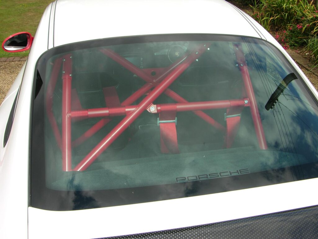
Benders Hub is not a tech inspector or an engineer. For cages, roll bars and chassis, confirm tube, wall, radius and any bend rules with your current rulebook and your inspector before you buy tube. Read our safety notes too.
How to check wall thinning on a test bend
You can’t see wall thinning from the outside. To know your real number, you need to measure it. There are two practical ways for a small shop.
Method 1: section a test bend
This is cheap and very clear. You bend a scrap piece, cut it, and measure the wall directly.
- Measure the straight tube. Check the wall at several points around a cut end. Tube wall isn’t perfectly even from the mill, so note the range.
- Bend a test piece. Use the same die, tube batch and setup as your real part.
- Mark the middle of the bend on the outside and inside.
- Cut across the bend at that mark with a saw. Deburr the cut gently so you don’t remove wall.
- Measure the outer wall at the extrados, then the inner wall at the intrados, and the sides.
- Compare. Thinning % = (original wall − bent wall) ÷ original wall × 100.
- Log it with the tube, die and date.
Calipers work for this, but their flat jaws don’t sit perfectly on the curved inside of a tube. A tube micrometer with a rounded anvil reads the inside curve more accurately. Either way, take a few readings and keep the smallest one on the outside.
Method 2: an ultrasonic thickness gauge
An ultrasonic gauge measures wall from the outside, with no cutting. You put a little couplant gel on the tube and press the probe against it. It’s handy for checking finished parts. Readings on small, curved tube can be tricky, so follow the gauge maker’s instructions and check it on a known piece of straight tube first.
A worked thinning calculation
Say your straight tube measures .120″ and the outside of your test bend measures .108″. The readings are made up to show the math. Then (.120 − .108) ÷ .120 = .012 ÷ .120 = 0.10, or 10% thinning. Don’t expect your measured thinning to match the stretch percentage for your die. That’s exactly why you measure.
How to limit wall thinning
You can’t stop the outer wall stretching. That’s how bending works. But you can keep thinning to a level your part can live with.
1. Choose a larger CLR
This is the biggest lever by far. As the table showed, stretch ≈ 1 ÷ (2D). Moving from 3D to 4D drops the geometric stretch from about 16.7% to 12.5%. If your design and rulebook allow a bigger radius, it’s the simplest fix.
2. Start with more wall
Thicker wall doesn’t stretch less, but it leaves more metal when it’s done. If the outside of the bend needs a certain minimum, starting with more wall gives you margin. Check your bender can handle it: heavier wall needs more force, and capacity charts set limits.
3. Pick a friendlier material or temper
Softer material stretches more evenly. For aluminum, Rogue Fab and The Fabricator both point to softer tempers as easier to bend than T6. For steel, follow your design or rulebook on grade.
4. Use mandrel support where you need it
A mandrel’s main job is to support the inside of the tube so it doesn’t flatten, kink or wrinkle. It doesn’t change the geometry: the outside still travels a longer path. For tight, thin-wall bends you’ll need one anyway. Read mandrel vs crush bending for the trade-offs.
| Lever | What it changes | Effect on thinning |
|---|---|---|
| Larger CLR | Geometric stretch | Directly lower |
| Thicker wall | Metal left after stretch | More margin |
| Softer temper | How evenly metal stretches | Less cracking risk |
| Mandrel | Inside support | Prevents collapse; geometry unchanged |
| Matched die | Support around the tube | Better shape, steadier results |
As an Amazon Associate I earn from qualifying purchases.
Eastwood High Capacity bender: choose the die first
Eastwood High Capacity Tube Bender (#21115)
A manual rotary-draw bender with published limits and a 1.75″ × 6″ CLR die, about 3.4D.
If you’re choosing a bender with wall thinning in mind, start with the die. A 1.75″ × 6″ CLR die works out to about 3.4D, or roughly 14.6% outer-fibre stretch by the geometry above. That’s in the range of common off-road and cage dies.
Who it’s for: builders bending 1.5″ to 1.75″ mild-steel bumpers, bars and frames who want clear published limits and a hydraulic upgrade path later.
Why it fits this topic: Eastwood publishes its wall limits, including a lower .090″ limit for 4130. Knowing your bender’s limits is part of managing wall at the bend.
- Type
- Manual rotary draw, hydraulic-ready
- Tube size
- Up to 2″ OD
- Mild steel
- Up to 2″ × .120″ wall
- 4130 chromoly
- Limited to .090″ wall
- Bend angle
- Up to 180° with 240° dies
- Sold separately
- Dies, handle and stand (check the listing)
Why we like it
- Clear published capacities
- 1.75″ × 6″ CLR 240° die available
- Air- or electric-hydraulic kits for later
Know before you buy
- No mandrel, so tight thin-wall bends aren’t its job
- Several parts are sold separately
- Lower chromoly wall limit than heavier benders
Die: 1.75″ × 6″ CLR 240° die. Affiliate links. See our disclosure.
Real-life lessons
These are composite stories. The same situations come up again and again in garage-fab forums and build threads.
A builder wants a tighter look on a bumper and swaps a die for one with a much smaller CLR on the same thin-wall tube. The bends look sharp, but the outside of each one looks rough, and one shows a hairline crack. The stretch had jumped far more than they expected.
Lesson: check stretch ≈ OD ÷ (2 × CLR) before you buy a tighter die, and test-bend the tube you’ll really use.
Someone building a roll bar wants to know how much wall is left at the bends. They bend a scrap piece from the same stick, cut it across the middle of the bend, and measure. The outer wall is thinner and the inner wall is thicker, just as the geometry predicts. They take the cut piece to their tech inspector to talk it through.
Lesson: a sectioned test bend answers questions no chart can.
A first-timer tries to make tight exhaust bends in thin-wall tube on a non-mandrel bender. The inside wrinkles and the section collapses. They switch to bought mandrel bends for the tight corners.
Lesson: very tight radii on thin wall need a mandrel machine. That’s what 1D, 1.5D and 2D exhaust bends are made on.
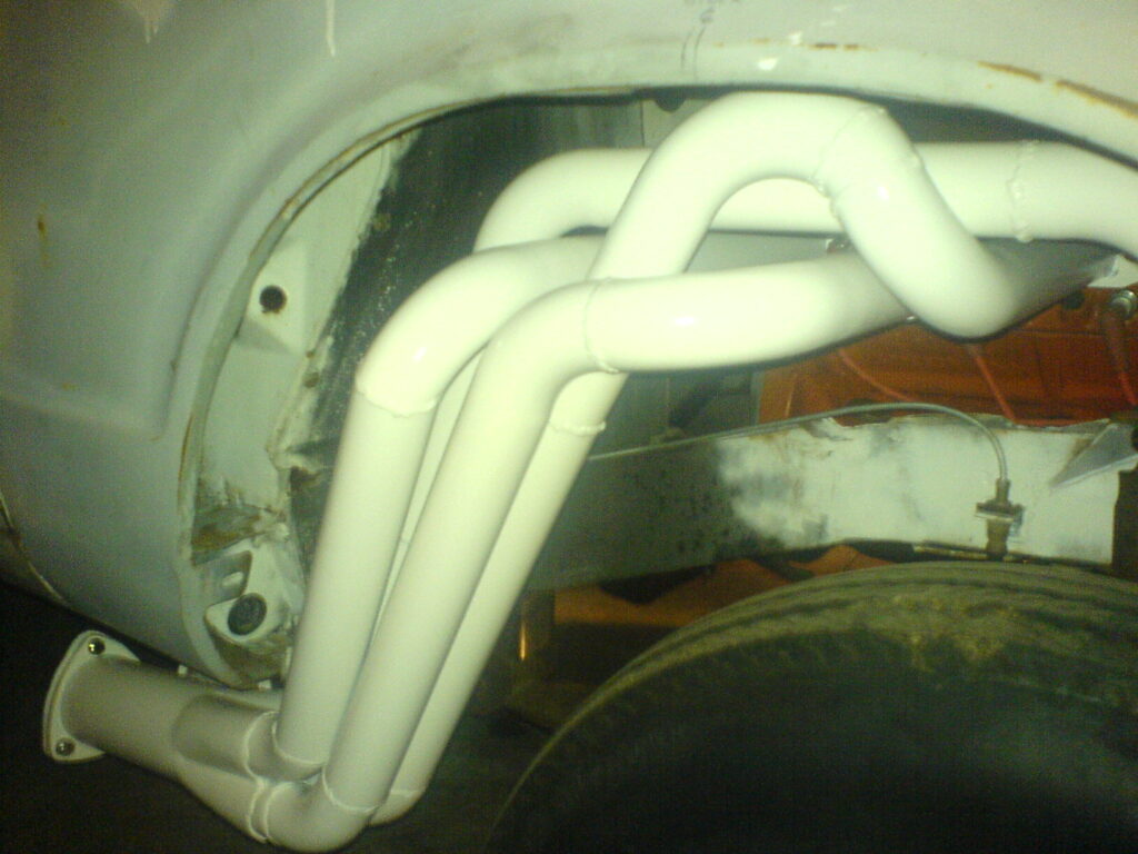
Common wall-thinning mistakes (and how to fix them)
Most wall-thinning problems come from a few habits. Here they are with the fix for each.
❌ Treating stretch as thinning. You see 14.6% stretch and assume the wall is 14.6% thinner.
✅ Fix: use stretch as a warning light. Measure real thinning on a sectioned test bend.
❌ Choosing a die only for looks. A tight CLR looks great but stretches the outer wall hard.
✅ Fix: work out D of bend and stretch first. Check your rulebook’s minimum radius.
❌ Trusting an unsourced thinning figure. A forum post says “bends thin about X%,” so you design to it.
✅ Fix: ignore numbers with no tube, die or source. Test your own setup.
❌ Measuring the wrong spot. You check wall at the cut end, not at the outside of the bend.
✅ Fix: measure at the extrados, mid-bend, and keep the smallest reading.
❌ Bending hard-temper aluminum tight. 6061-T6 on a tight radius cracks on the outside.
✅ Fix: use a larger radius, about 3.5D to 4D per Rogue Fab, or a softer temper if your design allows.
❌ Expecting a mandrel to stop thinning. You add a mandrel and assume the outer wall is safe.
✅ Fix: remember a mandrel supports shape. The outer path is still longer, so the wall still stretches.
Pro tips for managing wall thinning
These habits keep wall thinning predictable and stop it from surprising you on an important part.
- Know your D before you buy a die. Divide CLR by OD. Then halve one over that number to get the stretch. Our bend calculator does the first part for you.
- Keep a “known good” die per tube size. Once a die works well for a tube, stick with it for that size.
- Section one bend per new setup. One cut test piece per new tube, wall or die tells you more than any chart.
- Measure the straight tube too. Mill wall varies. Your thinning is the change from your tube’s starting wall.
- Check ovality at the same time. Thinning and flattening grow together on tight bends.
- Watch the surface. A rough texture on the outside of a bend shows the metal has been stretched hard. Take a closer look before you bend more.
- Ask before you bend safety parts. For cages, talk to your inspector about bend radius and wall before you buy tube.
Experienced builders often keep sectioned test bends, labelled with tube, wall and die, on a shelf. They’re a quick reference, and they’re great for showing a customer or inspector what’s inside a bend.
Frequently asked questions
What is wall thinning in tube bending?
It’s the outside wall of a bend getting thinner because it stretches over a longer path. The inside wall gets thicker because it’s squeezed into a shorter one.
How do you calculate outer wall stretch?
Use outer-fibre stretch ≈ OD ÷ (2 × CLR). For 1.75″ tube on a 6″ CLR, that’s 1.75 ÷ 12 ≈ 14.6%. It’s a geometric estimate, not a thinning prediction.
Is there a formula for wall thinning?
We didn’t find a simple, validated one for garage bending. Real thinning depends on material, tooling and how the metal flows. Measure it on a sectioned test bend or with an ultrasonic gauge.
Does a bigger bend radius reduce wall thinning?
Yes. Stretch ≈ 1 ÷ (2 × D of bend), so a larger CLR means less stretch on the outside of the bend. Going from 3D to 4D drops the geometric stretch from about 16.7% to 12.5%.
Does a mandrel prevent wall thinning?
Not really. A mandrel supports the inside so the tube doesn’t flatten or wrinkle. The outer wall still travels a longer path, so it still stretches.
Does bend angle affect wall thinning?
In the simple geometry, no. The stretch percentage depends on OD and CLR. A bigger angle just stretches a longer length of tube by the same percentage.
Your wall-thinning checklist
Run through this list before you commit to a die or bend an important part.
- I know my tube’s OD, wall and material
- I’ve worked out D of bend (CLR ÷ OD) for my die
- I’ve estimated outer stretch with OD ÷ (2 × CLR)
- My CLR meets any rulebook or design minimum
- I’ve checked my bender’s capacity for this wall and material
- I measured the straight tube’s wall at several points
- I sectioned a test bend from the same batch
- I measured the outer wall at mid-bend and kept the smallest reading
- I checked ovality on the same test piece
- I logged the results with tube, die and date
- For safety parts, I’ve talked to my inspector
Wall thinning sounds scary, but it’s just geometry plus a cut test piece. Pick your radius with care, measure once, and you’ll know exactly what’s inside your bends. ✅
Check your die before you buy it
Work out D of bend, wall factor and arc lengths in seconds. Or see the inner, outer and centerline arcs drawn for your tube.
Keep reading
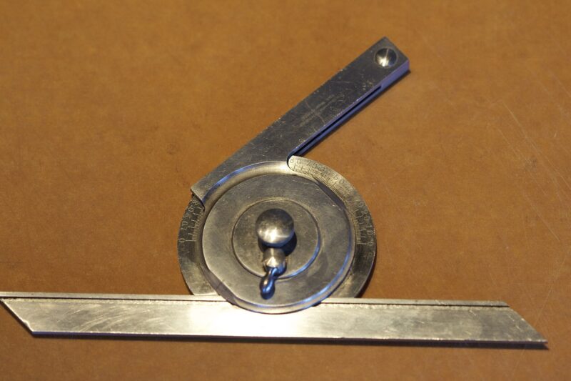
Ovality in Tube Bending: Formula, Measuring and Limits
Ovality in tube bending made simple: the formula, how to measure it with calipers, a worked example, and why your spec, not…
Exhaust Bend Radius 1D vs 1.5D vs 2D: Geometry and Fitment
Exhaust bend radius 1D vs 1.5D vs 2D explained: CLR = D × OD worked out for common pipe sizes, the space…
Tube Bending Wrinkles, Kinks and Flattening: Causes and Fixes
Fix tube bending wrinkles, kinks and flattening with symptom-to-cause-to-fix tables, clamp and pressure-die checks, and how to read die maker charts.