Tube Bend Rotation: Plane of Bend, Degree Wheels and Eliminating Twist
Tube bend rotation explained: plane of bend, 0°/90°/180° shapes, degree wheels, the angle-finder trap and simple checks to eliminate twist.

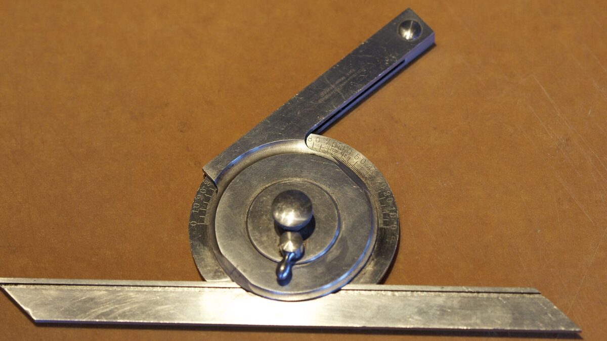
Your first bend is perfect. Your second bend is perfect too. But when you set the part on the floor, it rocks like a wobbly table. One leg points a few degrees off where it should. That’s twist, and it almost always comes from tube bend rotation: how far the tube turned, or didn’t turn, between bends.
Rotation is the part of tube bending nobody explains well. Bend angles get all the attention. But on any part with two or more bends, the rotation between them matters just as much. Get it wrong by a few degrees and a bumper won’t sit flat, a cage bar misses its mount, or you build a perfect left-side part when you needed the right.
This guide makes it simple. You’ll learn what “plane of bend” means, how to read rotation at a glance, how to set it with a degree wheel or angle finder, a hidden trap that catches a lot of builders, and how to check a finished part for twist. We’ll finish with a fully worked example.
Rotation is how far you turn the tube about its own axis between one bend and the next.
- 0° means both bends lie in the same plane and turn the same way, like a U.
- 180° means same plane, opposite way, like a Z or an offset.
- To eliminate twist, draw a straight reference line, set rotation with a degree wheel on the tube, and support long legs.
- Watch the trap: an angle finder on the previous leg reads true rotation only when that bend was 90°.
📋 In this guide
- What tube bend rotation means
- Rotation at a glance: 0°, 90° and 180°
- Why parts end up twisted
- Start with a reference line
- Setting tube bend rotation with a degree wheel
- The angle finder trap
- Worked example: a corner bar
- How to check a part for twist
- Real-life lessons
- Common rotation mistakes and fixes
- Pro tips to eliminate twist
- FAQ
- Your rotation checklist
What tube bend rotation means
Every bend happens in a flat plane. Picture a single 90° bend lying on a table. The two legs and the curve between them all sit on the tabletop. That flat surface is the bend’s plane of bend.
Now add a second bend. If you don’t turn the tube between bends, the second bend lands in the same plane as the first. The whole part still lies flat on the table. If you do turn the tube, the second bend tips up out of that plane. How far you turn it is the rotation between bends.
So a bent tube part is really described by three things for each bend:
- Where the bend starts along the tube (from your layout).
- How much it bends (the bend angle).
- Which way it bends, set by how far you rotate the tube from the bend before (the rotation).
Bend programs and CNC benders describe parts this way, as a list of feed lengths, rotations and bend angles. In a home garage, you do the same thing by hand. The first two items come from your layout. We cover those in our guide to how to lay out tube bends. This guide is all about the third.
What “twist” means
Twist is rotation you didn’t mean to have. Either the tube turned when it shouldn’t have, or it turned the wrong amount. Builders sometimes call the result a “dog leg.” It’s the most common reason a part with good bend angles still doesn’t fit.
A 30° rotation clockwise and a 30° rotation counterclockwise make mirror-image parts. On your sketch, write the direction as seen from one fixed spot, such as looking down the tube from the end that goes into the bender first.
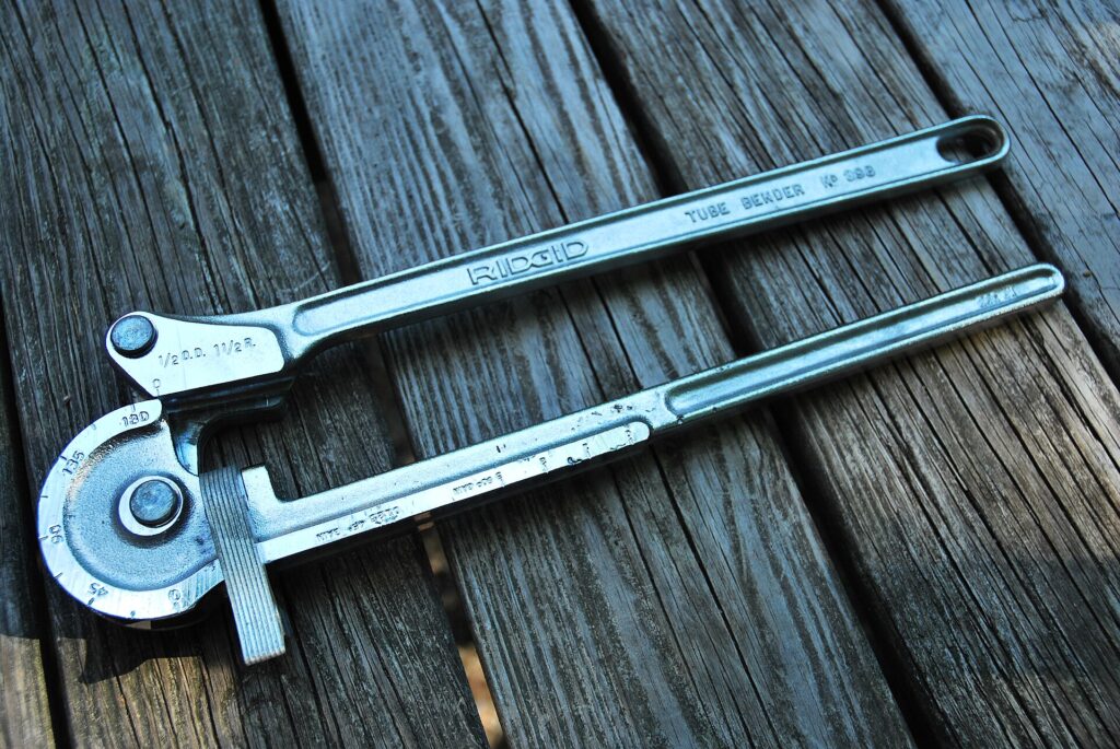
Rotation at a glance: 0°, 90° and 180°
Before you measure anything, learn to “read” rotation by eye. Most parts use one of three easy values. Once you can spot them, you’ll catch mistakes before you bend.
0° rotation: the U
Both bends sit in the same plane and turn the same way. You get a U, a hoop or a C shape. A simple roll hoop, a bed bar and a bumper with both wings swept back all use 0° rotation. You don’t turn the tube at all between bends. You just slide it to the next mark.
180° rotation: the Z
Both bends sit in the same plane but turn opposite ways. You get a Z, an S or an offset. Think of a bar that jogs sideways to clear something, then carries on parallel. You flip the tube exactly halfway round between bends.
90° rotation: the corner
The second bend turns straight out of the first bend’s plane. With two 90° bends, the three legs point along three edges of a box corner. Parts that wrap around a corner of a vehicle often have a 90° rotation somewhere.
Everything in between
Real parts often use odd values like 17° or 62°. Those come from a mock-up, a drawing or bend software. They’re the ones where careful measuring really pays off.
| Rotation | Shape with two bends | Lies flat on a table? | Typical parts |
|---|---|---|---|
| 0° | U, hoop, C | ✅ Yes | Hoops, bed bars, swept bumpers |
| 180° | Z, S, offset | ✅ Yes | Jogs, offsets, steps |
| 90° | Box corner | ❌ No | Bars that wrap a corner |
| Other | 3D shape | ❌ No | Cage bars, sliders, door bars |
Notice the “lies flat” column. Any part with only 0° and 180° rotations is a flat part. That gives you a very easy way to check for twist, which we’ll use later.
Why parts end up twisted
Twist rarely comes from one big mistake. It usually comes from a few small ones. Here are the common causes, and how to stop each.
The tube turns during the bend
If the clamp isn’t tight, or the tube and die are oily, the tube can rotate in the die as it’s pulled. A die that doesn’t match the tube’s real OD makes this worse. Clean the tube, use the right die and tighten the clamp firmly.
The tube turns between bends
This is the big one. When you unclamp and slide the tube to the next mark, it’s easy to let it roll a few degrees. Long legs make it worse. Their weight wants to swing down and turn the tube.
The reference is wrong
A wobbly reference line, an angle finder zeroed on the wrong surface, or a bender that isn’t level all feed you bad numbers. You set “0°” carefully, but it isn’t really 0°.
The measuring method is wrong
Measuring rotation off the previous leg with an angle finder only works in one special case. We’ll show you why in the angle finder section.
| Cause | What you see | Fix |
|---|---|---|
| Tube slips in the die | Reference line drifts during the bend | Clean tube, correct die, tight clamp |
| Tube rolls between bends | Reference line not where you left it | Support long legs; re-check the line |
| Bad reference line | Parts twist in the same way every time | Draw the line against a straightedge |
| Angle finder zeroed wrong | Every rotation off by the same amount | Zero on the bender or tube, not the floor |
| Measuring off a non-90° leg | Rotation larger than you set | Use a degree wheel, or correct the reading |
| Wrong direction | Mirror-image part | Write the direction on your sketch |
Pro-Tools has a whole blog post on this topic, “Don’t Get It Twisted”, if you want a second take.
Start with a reference line
The simplest anti-twist tool costs nothing. It’s a straight line drawn along the full length of the tube. Every other method in this guide builds on it.
Why it works
A straight tube has no “top” or “side.” The reference line gives it one. Before the first bend, you line it up with a fixed point, such as the top of the die. After that, the line tells you exactly how far the tube has turned. If it moves during a bend, you’ll see it. If it moves between bends, you’ll see that too.
How to draw a straight one
- Lay the tube in a length of angle iron or against a long straightedge so it can’t roll.
- Run a fine paint pen or marker along the edge of the angle, the full length of the tube.
- Check it by eye. Sight down the tube. The line should look perfectly straight, not spiraled.
- Add a second line exactly opposite, at 180°, if you’ll make Z-shaped parts. It makes flipping the tube easy.
Freehand lines tend to wander. A line that spirals a few degrees over the length of the tube will put that error into every rotation you set from it.
Use it at every bend
Line it up before the first bend. Check it after every bend. When you slide the tube to the next mark, look at it before you clamp. It takes a few seconds and catches most twist before it happens.
A straight reference line is the cheapest anti-twist tool in the shop. Draw it once, check it at every bend, and most twist never happens.
Setting tube bend rotation with a degree wheel
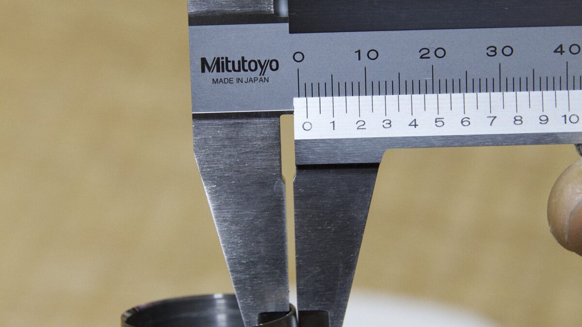
A degree wheel is a disc marked in degrees that clamps onto the tube or fits in its end. A fixed pointer on the bender, or a mark on the bench, shows the reading. Turn the tube, and the wheel turns with it. The pointer tells you exactly how far. Chassis-tool suppliers such as Mittler Bros sell degree wheels for this job.
Why a degree wheel beats the alternatives
A degree wheel measures rotation directly, about the tube’s own axis. It doesn’t care what angle the previous bend was, or which way the old leg points. That’s why it’s the most reliable way to set rotation by hand.
How to use one, step by step
- Fit the wheel on the free end of the tube, or clamp it on a straight section that won’t enter the die.
- Line up zero. With the reference line at your chosen spot, such as straight up, set the wheel to read 0°.
- Make bend 1. Bend, release and check the angle as usual.
- Slide to the next mark. Keep the wheel on the tube. Support the bent leg so it can’t swing.
- Rotate to the target. Turn the tube until the wheel reads the rotation on your sketch, in the right direction.
- Clamp and check. Clamp the tube, then glance at the wheel again before you bend. Clamping can nudge it.
A DIY version
No degree wheel? Print a paper protractor ring, glue it to a disc of plywood with a hole sized to slip over the tube, and add a small clamp. A pointer made from a strip of metal bolted to the bender completes it. It’s not fancy, but it reads rotation directly, which is what matters.
Mock-up tools
For parts with several odd rotations, a mock-up helps. Rogue Fab sells a PVC mock-up tool called the Prototractor that lists rotation between bends from 0.0° to 177.5° (Rogue Fab). Build the part in PVC, read the rotations, then set them with your degree wheel. You can also plan shapes in our geometry visualizer.
Rotation is only one of three numbers per bend. Use our bend calculator for tangent, arc and cut lengths before you start setting rotations.
The angle finder trap
Lots of builders set rotation with a digital angle finder laid on the previous leg. It’s quick, and everyone owns one. But it only reads the true rotation in one special case: when the previous bend was exactly 90°.
Why it goes wrong
Picture a bender that bends flat, side to side, with the tube sitting level. After the first bend, the old leg sticks out sideways. Roll the tube, and that leg tips up. The angle finder reads how steeply the leg slopes, not how far the tube rolled.
When the old bend is 90°, the leg sticks straight out from the tube. Then the slope and the rotation are the same number. When the old bend is shallower, the leg points partly along the tube. It can’t tip up as steeply, so the angle finder reads less than the real rotation.
The numbers
For a level tube in a bender that bends flat, the angle finder on the old leg reads: arcsin(sin of bend angle × sin of rotation). Here’s what that looks like.
| Previous bend | 15° rotation | 30° rotation | 45° rotation | 60° rotation | 90° rotation |
|---|---|---|---|---|---|
| 30° | 7.4° | 14.5° | 20.7° | 25.7° | 30.0° |
| 45° | 10.5° | 20.7° | 30.0° | 37.8° | 45.0° |
| 60° | 13.0° | 25.7° | 37.8° | 48.6° | 60.0° |
| 90° | 15.0° | 30.0° | 45.0° | 60.0° | 90.0° |
Read it like this. If your last bend was 45° and you want 30° of rotation, roll the tube until the angle finder on the old leg reads 20.7°, not 30°. Only the 90° row matches the rotation.
Worked check
Say you ignore this and roll a 45° leg until it reads 30°. What rotation did you really set? Solve for it: sin(rotation) = sin(30°) ÷ sin(45°) = 0.5 ÷ 0.7071 = 0.7071. That’s a rotation of 45°. You wanted 30°. The part is 15° off.
The table assumes the tube sits level and the bender bends side to side. If your bender bends up and down, the math changes. The safe rule works for every bender: use a degree wheel on the tube, or measure off a 90° leg only.
As an Amazon Associate I earn from qualifying purchases.
A digital angle gauge, used the right way
Wixey WR365 Digital Angle Gauge with Flip-Out Display
A small magnetic angle gauge with a zero button and a display you can tilt to read.
An angle gauge is still worth having. It just has to be used for the job it does well: reading bend angles and checking that a reference surface is level before you clamp. Zero it on the first leg, then read the second leg. Use the degree wheel and your reference line for rotation, as shown above.
Who it’s for: anyone who wants to read bend angles to a fraction of a degree and check that the bender and tube are level before each bend.
Why it’s useful here: the listing gives 0.1° resolution and ±0.2° accuracy. The zero function lets you measure relative to a leg instead of the bench, and the flip-out screen helps when the gauge sits on a tube.
- Resolution
- 0.1° (listing)
- Accuracy
- ±0.2° (listing)
- Range
- ±180° (listing)
- Display
- Flip-out, backlit
- Base
- Magnetic
Why we like it
- Zero-and-read workflow for bend angles
- Display flips up so you can read it on a tube
- Magnet holds it on steel tube
Know before you buy
- It reads tilt, not rotation around the tube, so it can’t replace a degree wheel
- Flat base sits on a line of contact on round tube
- Magnet won’t help on aluminum or most stainless
Alternative: Wixey WR300 Type 2 digital angle gauge. Affiliate links. See our disclosure.
Worked example: a corner bar
Let’s put it together with a part that has a 90° rotation: a bar that wraps around a box corner. Think of a bar that runs along a frame rail, turns up, then turns back across.
The setup
- Tube: 1.75″ OD mild steel, bent on a 6″ CLR die.
- Leg A: 20″ from its end to the first intersection point.
- Middle section: 24″ between the two intersection points.
- Leg B: 20″ from the second intersection point to its end.
- Bends: two 90° bends, with 90° of rotation between them.
Step 1: the layout numbers
For a 90° bend on a 6″ CLR die, the tangent length is 6″ and the arc length is 9.42″ (6 × 90 × 0.017453). So:
- Leg A straight: 20 − 6 = 14.00″
- Middle straight: 24 − 6 − 6 = 12.00″
- Leg B straight: 20 − 6 = 14.00″
- Cut length: 14 + 9.42 + 12 + 9.42 + 14 = 58.85″, using the unrounded arcs
Check it: the intersection lengths add up to 64″. Each 90° bend gains 2 × 6 − 9.4248 = 2.575″. Two bends gain 5.15″, and 64 − 5.15 = 58.85″. ✅
Step 2: mark the tube
- Bend 1 start: 14.00″ from end A
- Bend 1 end: 23.42″ (23-7/16″)
- Bend 2 start: 35.42″ (35-7/16″)
- Bend 2 end: 44.85″ (44-7/8″)
- End B: 58.85″ (58-7/8″)
Draw your reference line before marking. Write “rotate 90°” and the direction on the tube between the two bends.
Step 3: bend 1
Set the reference line at your zero spot, such as straight up, and zero the degree wheel. Make bend 1, allowing for your springback. Check it reads 90° after release.
Step 4: rotate 90°
Slide the tube to the bend 2 mark. Support leg A. Turn the tube 90° in the direction on your sketch. Because bend 1 was exactly 90°, you can double-check with an angle finder on leg A. In a flat-bending bender, leg A should now point straight up or straight down and read 90° from level.
Step 5: bend 2 and check
Make bend 2. Now the three straights should point along three edges of a box corner. Set the part on a flat surface on leg A and the middle section, and leg B should point straight up. Check it with a square.
Want to check the math first? Our tube bend length formula guide walks through tangent and arc lengths in more detail.
How to check a part for twist
Don’t wait until fit-up to find twist. Check each part as soon as it’s bent, while it’s still easy to remake.
The flat-table test (for flat parts)
Any part with only 0° and 180° rotations should lie perfectly flat. Set it on a flat welding table or a clean, flat floor. Press down on each corner in turn. If it rocks, it’s twisted. If every straight touches, it’s flat. This is the fastest check there is.
The square test (for 90° rotations)
Lay the part on one flat plane, like the bottom of the corner bar. Use a framing square against the leg that should stand up. If the leg leans, the rotation is off. Measure how far it leans at a known height to see how big the error is.
The angle test (for odd rotations)
For 3D parts, rest one bend’s plane flat on the table. Then check the next leg’s angle with an angle finder, and compare it with your mock-up or your plan. Use the table in the angle finder section if the bend before it wasn’t 90°.
What to do if it’s twisted
Small errors can sometimes be pulled into place during fit-up on non-critical parts. For anything structural, like a cage or a chassis tube, remake the part. Forcing a twisted tube into place builds stress into the joint. And for roll cages, your rulebook and your tech inspector have the final word. See our guide to building a roll cage.
When you rotate a part with long bent legs, they swing through a big arc. Keep your head and helpers out of the swing path, and support the legs so they can’t drop. Read our workshop safety notes.
Real-life lessons
These are composite stories. The same situations come up again and again in garage-fab forums and build threads. Every one of them is easy to avoid once you’ve seen it.
A builder bends a front bumper with two swept-back wings. Both bends are 0° rotation, so the part should lie flat. But they didn’t support the long first wing when they slid the tube to bend 2. The wing sagged and rolled the tube a few degrees. On the floor, the bumper rocks.
Lesson: support long legs between bends and check the reference line before you clamp.
Someone needs 30° of rotation after a 45° bend. They roll the tube until the angle finder on the old leg reads 30°. The real rotation is 45°, and the bar misses its mount by a long way.
Lesson: an angle finder on the old leg only reads true rotation after a 90° bend. Use a degree wheel.
A builder makes a perfect rock slider for the driver’s side, then makes the second one with the same numbers. It comes out identical, not mirrored, and won’t fit the passenger side.
Lesson: mirror parts need the rotation direction reversed. Write the direction on every sketch.
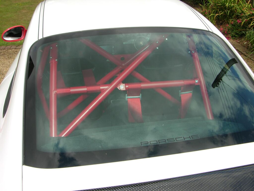
Common rotation mistakes (and how to fix them)
Most twisted parts come from a short list of mistakes. Here they are, with the fix for each.
❌ No reference line. You can’t see when the tube turns.
✅ Fix: draw a straight line along the tube against angle iron, and check it at every bend.
❌ Measuring rotation off a non-90° leg. The angle finder reads less than the real rotation.
✅ Fix: use a degree wheel on the tube, or correct the reading with the table above.
❌ Letting long legs hang. Their weight rolls the tube between bends.
✅ Fix: support the bent leg with a stand or a helper while you slide and clamp.
❌ Not writing the direction. You get a mirror image of the part you needed.
✅ Fix: note clockwise or counterclockwise, seen from a fixed end, on the sketch and the tube.
❌ Loose clamp or oily tube. The tube spins in the die as it bends.
✅ Fix: wipe the tube clean, use the right die and tighten the clamp firmly.
❌ Checking only at the end. By then, every bend has added error.
✅ Fix: check the reference line or degree wheel after every bend, not just the last one.
Pro tips to eliminate twist
These habits come up again and again among builders whose parts drop straight into place.
- 💡 Zero on the bender, not the floor. Garage floors slope. Set your angle finder to zero on the bender or the straight tube before bend 1, and take every reading the same way.
- 💡 Check flat sections as you go. After any pair of bends with 0° or 180° rotation, lay that section on a flat surface before the next bend.
- 💡 Mark rotations on the tube. Write each rotation and direction right on the tube between the bends, so you can’t forget.
- 💡 Use two reference lines. A second line at 90° or 180° gives you a quick visual check for common rotations.
- 💡 Mock up the hard ones. Build tricky parts in PVC or wire first and read the rotations off the mock-up.
- 💡 Keep notches in phase too. The notches on each end of a bar must line up with the bends. Our tube notching guide covers this.
- 💡 Log your results. Note any part that came out twisted and why. Patterns show up fast.
Experienced builders pick one zero at the start, usually the reference line straight up, and measure every rotation from it. They never “re-zero” halfway through a part. That way errors can’t stack up from bend to bend.
Frequently asked questions
What is tube bend rotation?
It’s how far you turn the tube about its own axis between one bend and the next. It sets which way each bend points. 0° keeps both bends in the same plane, turning the same way.
What is the plane of bend?
It’s the flat plane a single bend lies in, containing both straights and the curve between them. Rotation tips the next bend out of that plane.
How do I stop my tube parts from twisting?
Draw a straight reference line, tighten the clamp, support long legs between bends and set rotation with a degree wheel. Check each part on a flat surface as soon as it’s bent.
Can I set rotation with a digital angle finder?
Yes, but only by measuring off a leg whose bend was 90°. After a shallower bend, the reading is smaller than the real rotation. A degree wheel on the tube avoids the problem.
What’s the difference between 0° and 180° rotation?
Both keep the bends in one plane. At 0°, the bends turn the same way and make a U. At 180°, they turn opposite ways and make a Z or an offset.
Your rotation checklist
Run through this list before your next multi-bend part. If you can tick every box, you’re ready.
- My sketch shows every bend angle, every rotation and its direction
- I’ve drawn a straight reference line against angle iron
- I’ve picked one zero for the whole part, such as the line straight up
- My degree wheel or rotation indicator is on the tube and zeroed
- I only measure rotation off a leg whose bend was 90°, or I use the correction table
- The clamp is tight and the tube and die are clean
- I have a stand or helper to support long legs between bends
- I check the reference line after every bend
- I’ll test flat parts on a flat surface as soon as they’re bent
- For mirror parts, I’ve reversed the rotation direction
That’s rotation, demystified. Draw a good line, pick one zero, set each rotation directly on the tube and check as you go. Your parts will sit flat, line up and drop into place. 🔧
Plan the whole part before you bend
See bend geometry in 3D, then work out tangent, arc and cut lengths in seconds.
Keep reading
How to Build a Roll Cage: A Step-by-Step Garage Guide
How to build a roll cage step by step: rulebook first, then layout, templates, bending, notching, fit-up and an expert review before…
Bending Stainless Exhaust Tubing: Mandrels, Springback & Test Bends
Bending stainless exhaust tubing without wrinkles: when you need a mandrel, how to measure springback with a test bend, and how to…

Exhaust Tube Cut Length: Step-by-Step Maths for J-Bends and U-Bends
Work out exhaust tube cut length the easy way: arc and tangent formulas, plus three worked J-bend and U-bend examples with every…