How to Measure and Lay Out Tube Bends (With Worked Examples)
How to measure and lay out tube bends: centerline sketches, tangent and arc math, cut length, bend marks and a test bend, with two worked examples.

You’ve got a stick of tube, a bender and a part in your head. You make the first bend and it looks great. Then the second bend lands two inches off, and the whole piece is scrap. Sound familiar? Learning how to measure and lay out tube bends is what turns “close enough” into parts that drop right into place.
Good news: tube layout is mostly simple math plus a few habits. You need three numbers from your die and your sketch. Then you mark the tube, bend in order and check as you go. This guide walks you through it with two full worked examples, every number shown, so you can follow along with a calculator or our free tools.
We’ll cover the key terms (CLR, tangent, arc length and gain), how to measure the space, a step-by-step layout method, how to find where your bender really starts a bend, and template bending for shapes you can’t draw on paper. Grab a tape measure, and let’s go.
To lay out a bent tube part, work in centerline dimensions and use two formulas:
- Tangent length = CLR × tan(bend angle ÷ 2). For a 90° bend, it equals the CLR.
- Arc length = CLR × bend angle in radians (about CLR × degrees × 0.01745).
- Each straight = the centerline distance between intersections, minus the tangents at each end.
- Cut length = all straights + all arcs, plus a little trim. Then do a test bend to learn your bender’s real bend start and springback.
📋 In this guide
- Why layout beats guesswork
- The layout words you need
- How to measure the space
- How to measure and lay out tube bends: the method
- Worked example: a two-bend hoop
- Worked example: a bumper with 30° wings
- Finding your bender’s true bend start
- Template bending for tricky shapes
- Real-life layout lessons
- Common layout mistakes and fixes
- Pro tips for accurate parts
- FAQ
- Your layout checklist
Why layout beats guesswork
Bending without a layout is like cutting lumber without measuring. You might get lucky on a single bend. But every bend after the first depends on where the first one landed. Small errors add up fast.
Here’s what a proper layout gives you:
- The right cut length. Bends use up tube in a curve, so a bent part needs less tube than its outside measurements suggest. Layout tells you exactly how much to cut.
- Bend marks in the right place. You’ll know where each bend starts and ends on the straight tube, before you clamp it.
- Room to clamp. You’ll see early if a straight is too short for the bender’s clamp, so you can plan around it.
- Repeatable parts. Write the numbers down once and you can make a matching part, like the other side of a bumper, every time.
Layout matters most on parts where tubes meet other tubes: roll bars, cages, bumpers, sliders and frames. A bar that’s half an inch long won’t fit between its mounts. A bend that starts too early throws every later bend off. And tube isn’t cheap.
The math is not hard. If you can multiply and subtract, you can lay out tube bends. And if you’d rather skip the arithmetic, our free bend calculator does it for you. It still helps to understand what it’s doing, so you can spot a bad number before it costs you a stick of tube.
Every bend after the first depends on where the first one landed. Layout is how you make the first one land in the right place.
The layout words you need
Tube layout uses a handful of terms. Learn these and every layout guide, manual and calculator will make sense. You’ll also find them in our glossary.
Centerline radius (CLR)
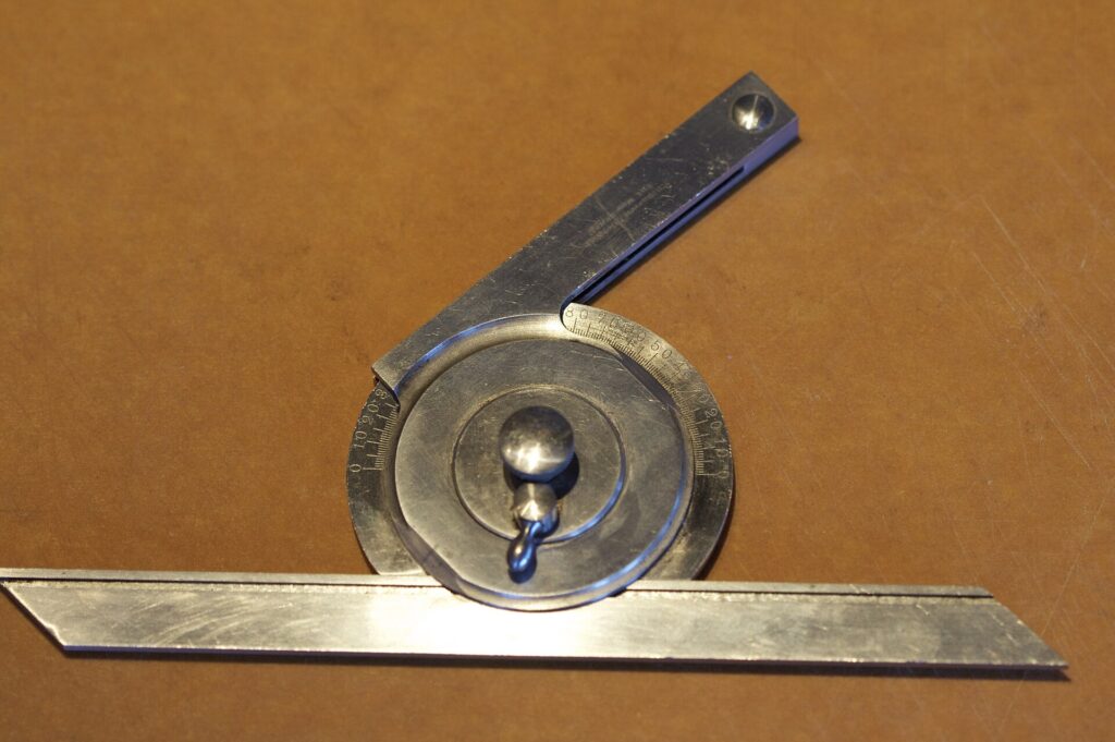
The CLR is the radius of the bend, measured to the center of the tube. Your die sets it. A 6″ CLR die always makes a 6″ CLR bend in the tube it’s made for. Read more in our guide to bend radius.
Tangent points and tangent length
A bend starts and ends at tangent points. That’s where straight tube turns into curve. Now picture the two straights extended until they cross. That crossing is the intersection point. The distance from a tangent point to the intersection is the tangent length. It equals CLR × tan(angle ÷ 2). For a 90° bend, the tangent length equals the CLR.
Arc length
The arc length is the tube used up inside the bend, measured along the centerline. It’s CLR × angle in radians. JD2’s manual writes it as CLR × degrees × .0175 (JD2 Model 32 manual). The exact constant is 0.017453, so JD2’s rounded number reads a little long.
Gain
A bent part is shorter than the sum of its intersection-to-intersection measurements. The difference is called gain. Per bend, it’s 2 × tangent − arc. Watch out, though. Some people also use “gain” for the stretch a tube picks up in a particular bender. That kind is machine- and die-specific, so you find it with a test bend. “Setback” is another word that different sources define differently, so we avoid it.
| Term | What it means | Formula | 90° bend on a 6″ CLR die |
|---|---|---|---|
| CLR | Bend radius to the tube’s center | Set by the die | 6.00″ |
| Tangent length | Tangent point to intersection point | CLR × tan(angle ÷ 2) | 6.00″ |
| Arc length | Tube used inside the bend | CLR × angle in radians | 9.42″ |
| Gain | Tube “saved” by the bend | 2 × tangent − arc | 2.58″ |
| Springback | How much the tube relaxes after release | Measured with a test bend | Varies |
Want the full derivation? See our tube bend length formula guide.
How to measure the space
Before you touch the tube, you need a sketch with dimensions. The trick is to think in centerlines. The formulas above all work on the tube’s centerline, so your sketch should too.
Measure to centerlines, not edges
Tape measures hook onto edges, so you’ll often measure outside-to-outside or inside-to-inside. Convert them like this:
- Outside-to-outside width minus one tube OD = centerline width.
- Inside-to-inside width plus one tube OD = centerline width.
- Height to the top of a bar minus half the OD = height to its centerline.
For example, a hoop in 1.75″ tube that measures 41.75″ across the outside is 40″ wide on the centerline. The same hoop measures 38.25″ across the inside. Add 1.75″ and you’re back to 40″.
Find the intersection points
Next, mark where each pair of straights would meet if there were no bend. Those are your intersection points. Measure the distances between them along each straight. On a simple hoop, that’s the leg height and the width. On a bumper, it’s each section’s length from corner to corner.
Note the angles and the die
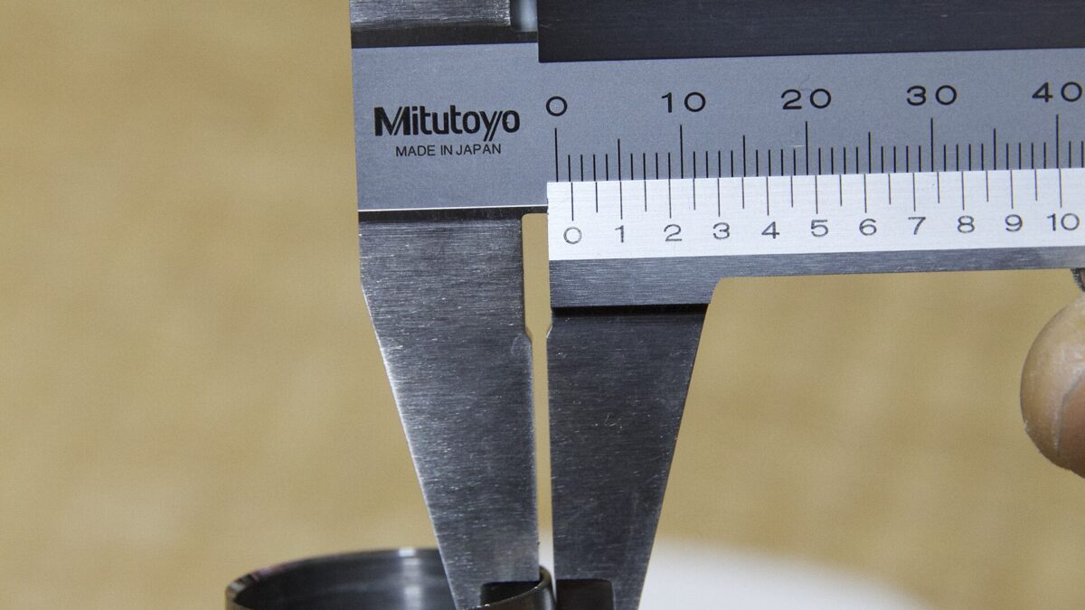
Write down each bend angle and the CLR of the die you’ll use. Check your tube OD with calipers, too. Tube and pipe sizes are not the same thing. 1-1/2″ pipe actually measures 1.900″ across the outside.
Draw the part on paper or cardboard. Label every centerline length between intersection points and every bend angle. Number the bends in the order you’ll make them. This one sheet becomes your whole layout.
Building a cage or roll bar? The rulebook sets your tube size, wall and minimum bend radius. SCCA Time Trials, for example, says cage bends must have a centerline radius of at least three times the tube diameter (SCCA Time Trials). Check your own rulebook first, and see our roll cage bend radius rule guide.
How to measure and lay out tube bends: the method
This is the routine we’ll use in both worked examples. It works for any part where all the bends are in one plane. Parts with bends in different directions add one more step, rotation. We cover that in our guide to tube bend rotation and twist.
- Sketch the part in centerlines. Write the distance between each pair of intersection points and each bend angle.
- Work out each tangent length. Tangent = CLR × tan(angle ÷ 2). For 90°, it’s just the CLR.
- Work out each straight. Take each centerline distance and subtract the tangent at each end that touches a bend.
- Work out each arc. Arc = CLR × angle in radians, or CLR × degrees × 0.017453.
- Add it up. Cut length = all straights + all arcs. Add trim allowance on the ends if you want to square them up later.
- Mark the tube. From one end, mark each bend start and bend end in order. Draw a straight reference line along the tube too.
Tools you’ll need
A tape measure, a fine marker or soapstone, calipers and a digital angle finder cover most layout work. The bender and die set your CLR, so pick those first. Here are two Amazon options that fit the examples in this guide.
As an Amazon Associate I earn from qualifying purchases.
Eastwood 1.75″ × 6″ CLR die
Eastwood 1.75″ × 6″ CLR 240° Die
A 1.75″ OD die with a 6″ centerline radius for the Eastwood High Capacity bender.
Both worked examples below use a 1.75″ tube on a 6″ CLR die, a very common off-road and cage combination. This is Eastwood’s version for its High Capacity bender. The 240° die lets that bender reach 180° bends.
Who it’s for: Eastwood High Capacity owners building in 1.75″ tube. Owners of other benders need a die made for their machine.
- Tube OD
- 1.75″
- CLR
- 6″
- Die
- 240° (bends up to 180° on the High Capacity)
- Fits
- Eastwood High Capacity bender
Bender: Eastwood High Capacity tube bender. Affiliate links. See our disclosure.
Eastwood High Capacity tube bender
Eastwood High Capacity Tube Bender (#21115)
A manual rotary-draw bender that can take air- or electric-hydraulic power later.
A repeatable bender makes layout pay off. If the bender starts each bend in the same place every time, your marks work every time.
Who it’s for: builders who want a manual bender for 1.5″ to 2″ tube with an upgrade path. Note that 4130 is limited to a thinner wall than mild steel.
- Tube size
- 3/4″ to 2″ OD
- Mild steel
- Up to 2″ × .120″ wall
- 4130 chromoly
- Limited to .090″ wall
- Bend angle
- Up to 180° with 240° dies
- Sold separately
- Dies, handle and stand (check the listing)
Affiliate link. See our disclosure. Compare other machines in our home garage bender guide.
Worked example: a two-bend hoop
Let’s lay out a simple hoop, the kind you’d use for a bed bar, a light hoop or a kart frame. It has two legs, a top bar and two 90° bends. The same method works for a roll bar main hoop, but there the rulebook sets the tube and radius.
The setup
- Tube: 1.75″ OD × .120″ wall mild steel.
- Die: 6″ CLR.
- Width: 40″ on the centerline between the legs.
- Height: 30″ from the leg ends to the centerline of the top bar.
- Bends: two 90° bends, both in the same direction and the same plane.
Quick health check first. D of bend is CLR ÷ OD: 6 ÷ 1.75 = 3.43. Wall factor is OD ÷ wall: 1.75 ÷ .120 = 14.6. A 3.4D bend sits right in the range of common off-road dies, so this is a normal combination.
Step 1: tangent length
For a 90° bend, tangent = CLR × tan(45°) = 6 × 1 = 6.00″.
Step 2: the straights
- Each leg: 30″ − 6″ tangent = 24.00″. Only one end of each leg touches a bend.
- Top bar: 40″ − 6″ − 6″ = 28.00″. Both ends touch a bend.
Step 3: the arcs
Arc = 6 × 90 × 0.017453 = 9.42″ per bend (9.4248″ before rounding). With JD2’s .0175 constant you’d get 9.45″. That’s only 0.025″ more per bend, but it adds up on a part with many bends.
Step 4: cut length
Cut length = 24.00 + 9.42 + 28.00 + 9.42 + 24.00 = 94.85″, using the unrounded arcs. Check it with gain: the intersection measurements add up to 30 + 40 + 30 = 100″. Each 90° bend gains 2 × 6 − 9.4248 = 2.575″. Two bends gain 5.15″. And 100 − 5.15 = 94.85″. ✅ The two methods agree.
Step 5: the bend marks
| Mark (from end A) | Decimal | Nearest 1/16″ | What happens here |
|---|---|---|---|
| Bend 1 start | 24.00″ | 24″ | Leg A ends, first bend begins |
| Bend 1 end | 33.42″ | 33-7/16″ | Top bar begins |
| Bend 2 start | 61.42″ | 61-7/16″ | Top bar ends, second bend begins |
| Bend 2 end | 70.85″ | 70-7/8″ | Leg B begins |
| End B (cut) | 94.85″ | 94-7/8″ | End of the tube |
Each mark is worked from the exact arc and rounded once at the end. That’s why adding the rounded numbers can be off by 0.01″. Cut the tube to 94-7/8″, or a little longer if you want to trim the legs to fit.
Step 6: bend it
Draw a reference line along the tube. Line up the bend 1 start mark with your bender’s start point. Bend to 90° plus your springback. Then slide the tube to bend 2, keep the reference line in the same spot so the second bend stays in the same plane, and bend again. Both bends go the same direction, so the tube doesn’t rotate between them.
Enter 1.75″ OD, a 6″ CLR and two 90° bends into our bend calculator to check these numbers. Then use the geometry visualizer to see where the tangent points and arcs fall.
Worked example: a bumper with 30° wings
Not every bend is 90°. Let’s try a front bumper with a straight center section and two wings bent back 30°. Same 1.75″ tube, same 6″ CLR die.
The setup
- Center section: 36″ between the two intersection points.
- Each wing: 14″ from the intersection point to the end of the tube.
- Bends: two 30° bends, same direction, same plane.
The math
- Tangent: 6 × tan(15°) = 6 × 0.2679 = 1.61″.
- Arc: 6 × 30 × 0.017453 = 3.14″.
- Each wing straight: 14 − 1.61 = 12.39″.
- Center straight: 36 − 1.61 − 1.61 = 32.78″.
- Cut length: 12.39 + 3.14 + 32.78 + 3.14 + 12.39 = 63.85″, using the unrounded values.
Check with gain: 14 + 36 + 14 = 64″. Each 30° bend gains only 2 × 1.608 − 3.142 = 0.074″. Two bends gain 0.15″, and 64 − 0.15 = 63.85″. ✅ Notice how small the gain is on a shallow bend. On a 90° bend it was 2.58″.
| Mark (from end A) | Decimal | Nearest 1/16″ |
|---|---|---|
| Bend 1 start | 12.39″ | 12-3/8″ |
| Bend 1 end | 15.53″ | 15-9/16″ |
| Bend 2 start | 48.32″ | 48-5/16″ |
| Bend 2 end | 51.46″ | 51-7/16″ |
| End B (cut) | 63.85″ | 63-7/8″ |
How tangent and gain change with angle
As before, each mark above is worked from unrounded values. Here’s the same 6″ CLR die at different bend angles. Use it to sanity-check your own math.
| Bend angle | Tangent length | Arc length | Gain per bend |
|---|---|---|---|
| 15° | 0.79″ | 1.57″ | 0.01″ |
| 30° | 1.61″ | 3.14″ | 0.07″ |
| 45° | 2.49″ | 4.71″ | 0.26″ |
| 60° | 3.46″ | 6.28″ | 0.65″ |
| 90° | 6.00″ | 9.42″ | 2.58″ |
One handy shortcut: on a 6″ CLR die, each degree of bend uses 0.1047″ of tube. Rogue Fab rounds that to 0.105″ per degree in its Bending 101 guide (Rogue Fab).
Finding your bender’s true bend start
Your math says the bend starts at 24.00″. But where does your bender actually start bending, relative to your mark? Every bender and die is a bit different. The only way to know is a test bend on scrap.
The test bend, step by step
- Cut a scrap piece of the same tube you’ll use for the real part.
- Mark it 20″ from one end. Line that mark up with the die’s start point, the way your manual describes.
- Bend to a true 90°. Overbend, release and check with a digital angle finder until it reads 90° after springback.
- Lay it flat and measure. Measure from the cut end of the short leg to the outside face of the other leg. Use a square against that leg.
- Compare. With a 6″ CLR and 1.75″ tube, you’d expect 20 + 6 + 0.875 = 26.875″ (26-7/8″).
- Record the difference. If you measure, say, 27.125″, the bend started a quarter-inch late. Move future start marks a quarter-inch toward the tube end.
Write that offset on your bender or in a notebook, along with the tube and die. It folds any stretch and die quirks into one number you can trust.
Springback
Tube relaxes a little after you release the bend. That’s springback. Rogue Fab shows a mild-steel bend that read 86.5° after release when 90° was the target. JD2’s Template Bending Tutorial suggests 3–4° should be enough for its example material (JD2 tutorial). And JD2 says 4130 springs back about twice as much as mild steel of the same size and wall. Your number will be different, so measure it on your test piece. See our springback guide for more.
Springback and bend start can change between tube batches, materials and dies. Do a fresh test bend whenever any of those change. A short scrap piece is cheaper than a ruined part.
Template bending for tricky shapes
Some parts are hard to draw on paper. Think of a hoop that has to follow a curved roofline, or a bar that dodges a steering column. For these, many builders use template bending. You make the shape first in something cheap and easy to bend, then copy it in steel.
What to make a template from
- Stiff wire or welding rod. Bend it by hand to the shape you need, right in the vehicle.
- PVC pipe and fittings. Good for parts with several bends. Rogue Fab sells a PVC mock-up tool called the Prototractor that measures the rotation between bends.
- Cardboard. Great for flat parts like bumpers. Trace the shape, then measure off it.
How to read the template
- Mark the straights. Find where each straight section of the template begins and ends.
- Extend the straights. Lay the template on a flat surface and extend each straight with a ruler until they cross. Those crossings are your intersection points.
- Measure the angles. Use a protractor or digital angle finder on each pair of straights.
- Measure between intersections. These are your centerline lengths.
- Run the normal layout. Now use the same tangent, arc and cut-length steps from the examples above.
Remember that your template’s own bend radius doesn’t matter. Only the straights, the intersection points and the angles carry over. Your die sets the real radius.
JD2 publishes a free Template Bending Tutorial (PDF) on this method. It’s worth a read before your first template part.
Real-life layout lessons
These are composite stories. The same situations come up again and again in garage-fab forums and build threads. Each one is easy to avoid once you’ve seen it.
A builder measures a truck bed outside-to-outside, 41.75″, and lays out the hoop as if that were the centerline width. The finished hoop is 1.75″ too wide and won’t drop onto the mounts.
Lesson: convert every measurement to centerlines before you do any math.
Someone lays out a bumper perfectly on paper but never checks where their bender starts the bend. Every bend starts a little late. The center section comes out long and the wings miss the frame horns.
Lesson: do one test bend, measure it and apply the offset to every mark.
A builder cuts a part to the exact length and starts bending. The last straight turns out too short for the clamp block, so the final bend can’t be made. The part goes in the scrap pile.
Lesson: check clamp room on every straight. Leave extra on a short end and trim it after bending.
Notice the pattern. None of these builders made a math error in the formulas. Each one skipped a check: centerlines, the test bend or clamp room. A two-minute check would have saved each part.
Common layout mistakes (and how to fix them)
Most layout errors come from a short list. Here they are, with the fix for each.
❌ Mixing edge and centerline measurements. The part comes out one OD too wide or too narrow.
✅ Fix: convert every number to centerlines on your sketch before you start.
❌ Adding the outside measurements as the cut length. The tube is too long because you ignored gain.
✅ Fix: cut length = straights + arcs. Check it with intersection total − gain.
❌ Using the wrong constant. One layout page online gives 0.001745, which is ten times too small.
✅ Fix: use 0.017453 per degree, or convert degrees to radians first.
❌ Rounding at every step. Small rounding errors stack up over several bends.
✅ Fix: keep full numbers in the calculator and round only the final marks.
❌ Skipping the test bend. You don’t know where your bender really starts a bend.
✅ Fix: bend a scrap piece, measure it and record the offset and springback.
❌ No reference line. The tube rotates between bends and the part twists.
✅ Fix: draw a straight line along the tube and keep it lined up at every bend.
Pro tips for accurate parts
These habits come up again and again among builders who make parts that fit the first time.
- 💡 Mark both ends of every bend. A start mark and an end mark let you check that the bend landed where it should.
- 💡 Measure after each bend. Check the first leg before you make the second bend. Fixing a plan is easier than fixing a part.
- 💡 Bend from the tight end. If one straight is short, think about which end to start from so the clamp always has enough tube.
- 💡 Keep a die card. For each die, write the CLR, the bend start offset, the springback per material and any quirks.
- 💡 Lay out symmetric parts from the center. On a hoop or bumper, find the center mark first and measure out both ways. It keeps both sides equal.
- 💡 Leave trim. Add a little extra length on ends that will be notched or cut to fit. Our tube notching guide covers the fit-up side.
- 💡 Use paint pen, not tape. A thin, crisp line is easier to line up than the edge of masking tape.
Experienced builders keep a single sheet for each part: the sketch, the math, the marks and the offset they used. When they need a second bumper or a matching bar, they just repeat the sheet.
Frequently asked questions
How do you measure and lay out tube bends?
Sketch the part in centerline dimensions. Work out each tangent (CLR × tan of half the angle), each straight (distance between intersections minus tangents) and each arc (CLR × angle in radians). Add straights and arcs for the cut length, then mark bend starts from one end.
How much tube does a 90° bend use?
The arc length is CLR × 1.5708. On a 6″ CLR die, that’s about 9.42″ of tube inside the bend.
What is gain in tube bending?
Geometric gain is the difference between the sum of intersection measurements and the real cut length: 2 × tangent − arc per bend. Some people also use “gain” for stretch in a specific bender, which you find with a test bend.
Where does the bend start on a tube bender?
It depends on the bender and die. Line up your mark the way your manual describes, then do a test bend on scrap and measure it to find your real offset.
What is template bending?
You make the shape first in wire, PVC or cardboard, then measure the straights, intersection points and angles off the template and lay out the steel part from those numbers.
Your layout checklist
Run through this list before you cut or bend. If you can tick every box, you’re ready.
- My sketch shows centerline lengths between intersection points
- I’ve converted every outside or inside measurement to centerlines
- I’ve measured the real tube OD with calipers
- I know my die’s CLR and checked it against any rulebook minimum
- I’ve worked out tangent, straight and arc lengths for every bend
- My cut length matches both methods: straights + arcs, and intersections − gain
- Every straight is long enough for my bender’s clamp, or I’ve left extra
- I’ve done a test bend and know my bend start offset and springback
- A reference line runs the full length of the tube
- Bend start and end marks are on the tube, numbered in order
That’s the whole method. Think in centerlines, do the simple math, test once on scrap and mark carefully. Do that, and your next bent part will drop into place like it was made for it. 🔧
Let the tools do the math
Check your tangent, arc and cut lengths in seconds, then see the bend geometry before you touch the tube.
Keep reading
JD2 Model 32 vs Rogue Fab M605: Specs Compared Side by Side
JD2 Model 32 vs Rogue Fab M605, compared from published specs: capacity, power, dies, floor space and the M605 wall-rating conflict.
Exhaust Bend Radius 1D vs 1.5D vs 2D: Geometry and Fitment
Exhaust bend radius 1D vs 1.5D vs 2D explained: CLR = D × OD worked out for common pipe sizes, the space…
Tube Bending Wrinkles, Kinks and Flattening: Causes and Fixes
Fix tube bending wrinkles, kinks and flattening with symptom-to-cause-to-fix tables, clamp and pressure-die checks, and how to read die maker charts.