Ovality in Tube Bending: Formula, Measuring and Limits
Ovality in tube bending made simple: the formula, how to measure it with calipers, a worked example, and why your spec, not a chart, sets the limit.

Your bend looks great from across the garage. Then you run a finger around it and feel it: the tube isn’t quite round anymore. It’s a little flat on the outside of the bend and a little wide at the sides. That change in shape has a name. It’s ovality in tube bending, and every bent tube has some of it.
A little ovality is normal. Too much can weaken a part, choke flow in an exhaust, stop a clamp from fitting, or fail an inspection. The tricky part is that there’s no single “safe” number. The limit comes from your drawing, your customer, your code or your rulebook.
This guide keeps it simple. You’ll learn what ovality is, why tube goes oval in a bend, and the formula everyone uses. Then we’ll measure it with plain calipers, work a real example step by step, and cover the fixes that keep your tube round.
Ovality is how far a bent tube’s cross-section has gone out of round.
- Formula: ovality % = (Dmax − Dmin) ÷ Dnominal × 100. Dmax and Dmin are the largest and smallest outside diameters you measure at one spot in the bend.
- Measure it with calipers at the middle of the bend, turning the jaws to find the biggest and smallest readings.
- There’s no universal limit. Your spec, customer or rulebook sets it. Tighter radii, thinner wall, loose dies and ram benders all make it worse. A rotary-draw bender with a matched die is the usual garage fix.
📋 In this guide
What is ovality in tube bending?
Ovality is a measure of how far a tube’s cross-section has drifted from a perfect circle. Before bending, round tube is close to round. After bending, the section at the bend is usually a bit oval, like an egg seen end-on.
You’ll hear a few names for the same thing:
- Ovality or ovalization: the most common terms in shops and specs.
- Out-of-round: plain-English version, often used on drawings.
- Flattening or tube flattening percentage: used when the tube has clearly squashed in one direction.
- Deformation: some bender makers use this word for the same idea.
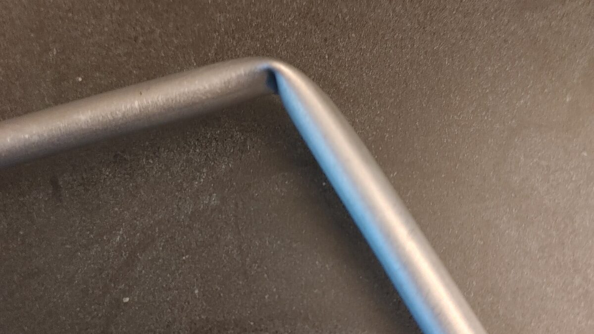
Ovality is different from two other bend defects. Wrinkles are ripples on the inside of the bend. A kink is a sharp collapse where the tube folds. Ovality is a smoother change in shape. You often can’t see small amounts by eye, which is why you measure it.
Here’s the key idea: ovality is always measured at one cross-section. You pick a spot along the bend, find the biggest and smallest outside diameters at that spot, and compare them. It’s a number for that location, not for the whole part.
If you want the background terms, like centerline radius (CLR) and D of bend, our glossary and our centerline radius guide explain them in plain English.
Why ovality matters
A little ovality rarely hurts a garage part. But it’s worth understanding why specs care, so you know when to pay attention.
Strength and stiffness
A round tube resists bending equally in every direction. Once it goes oval, the flattened direction gets weaker. In structural work, like frames and cages, you want the tube to keep the shape the designer assumed. That’s one reason rulebooks and engineers care about bend quality, not just tube size.
Flow
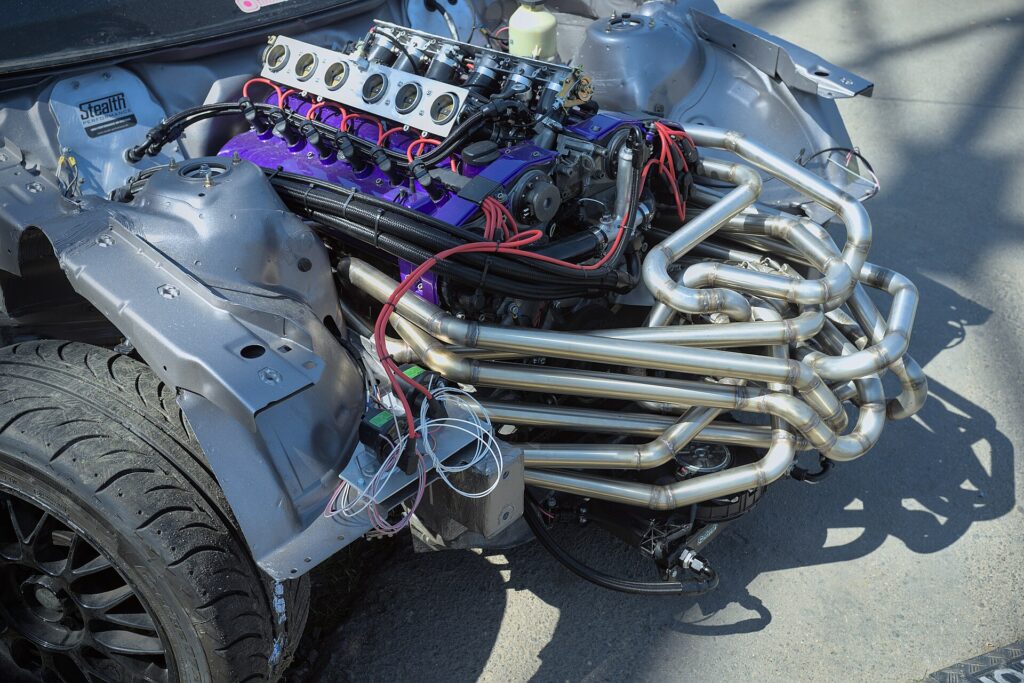
In exhaust, intake and fluid lines, an oval section changes the flow area and shape. The tube is no longer the clean round passage you paid for. That’s a big reason exhaust builders favor mandrel bends.
Fit-up
Clamps, couplers, slip joints and V-band flanges expect round tube. An oval section near the end of a bend may not slide into a coupler, and a clamp may not seal. Notching is harder too, because a hole saw expects a round tube to saddle onto.
Looks and inspection
Flattened bends just look worse. On a show part or a customer job, that matters. And on spec work, ovality is often a line item on the inspection sheet. If it’s over the limit, the part fails, however good it looks.
| Where it shows up | What ovality can do | Who cares most |
|---|---|---|
| Cages and chassis | Changes the tube’s section in the bend | Racers, tech inspectors, engineers |
| Exhaust and intake | Changes flow area and shape | Performance builders |
| Joints and clamps | Couplers and clamps don’t fit or seal | Anyone joining tube near a bend |
| Show and customer parts | Visible flat spots | Customers, you |
| Spec work | Fails inspection if over the limit | Shops working to drawings |
Why tube goes oval in a bend
When you bend a tube, the outside wall is stretched and the inside wall is squeezed. Both walls try to take the easiest path. The stretched outer wall pulls in toward the tube’s center. The squeezed inner wall pushes in toward the center too. The result is a section that flattens in the plane of the bend and widens at the sides.
So in most bends, the smallest diameter runs from the inside of the bend to the outside. The largest diameter runs across, side to side. That’s a handy starting point when you measure. But always check by turning the calipers, because the real max and min can sit at a slight angle.
What makes it worse
- Tight bends. A low D of bend (CLR ÷ OD) means more stretch and squeeze. Pro-Tools puts the practical minimum CLR without a mandrel at about 3 × OD.
- Thin wall. A high wall factor (OD ÷ wall) means less wall to hold the shape.
- Loose die fit. If the die groove is bigger than the tube, nothing supports the sides. This happens when pipe dies meet tube. A 1-1/2″ pipe die is made for 1.900″ OD, not 1.5″ tube.
- The wrong bender. Ram-style “pipe benders” push the middle of the tube with little side support. Harbor Freight’s own manual for its 12-ton bender says it isn’t meant for thin-wall pipe such as conduit or exhaust (manual).
- No inside support. Without a mandrel, thin-wall tube on a tight radius has nothing inside to stop it collapsing.
Our guide to wall factor and D of bend goes deeper on those two numbers. And our wrinkles, kinks and flattening guide covers the other defects that often travel with ovality.
The ovality formula, explained
The formula most bending references use is short:
Ovality % = (Dmax − Dmin) ÷ Dnominal × 100
Here’s what each part means:
- Dmax is the largest outside diameter you measure at one spot in the bend.
- Dmin is the smallest outside diameter at that same spot.
- Dnominal is the tube’s nominal size: the OD it’s sold as, like 1.750″.
This form appears in trade and academic sources, including a measurement paper presented at an IMEKO TC14 conference (2007). In words: take the difference between the widest and narrowest readings, divide by the size the tube is supposed to be, and turn it into a percentage.
Watch out for other versions
Not every source divides by the nominal OD. Engineers Edge, for example, also lists a version that divides by the sum of the two readings, (Dmax + Dmin). That gives a smaller percentage from the same measurements. Your spec may also define it its own way. None of these is “wrong.” They’re just different definitions.
| Version | Divide the difference by | Notes |
|---|---|---|
| Nominal OD (most common in bending) | Dnominal | The formula this guide uses |
| Sum of readings | Dmax + Dmin | Listed by Engineers Edge; gives roughly half the number |
| Your spec’s definition | Whatever the drawing or code states | Always wins on that job |
If a drawing or customer gives an ovality limit, check which formula they mean. A part can pass under one definition and fail under another. When in doubt, ask, and write the formula on your inspection sheet.
How to measure ovality with calipers
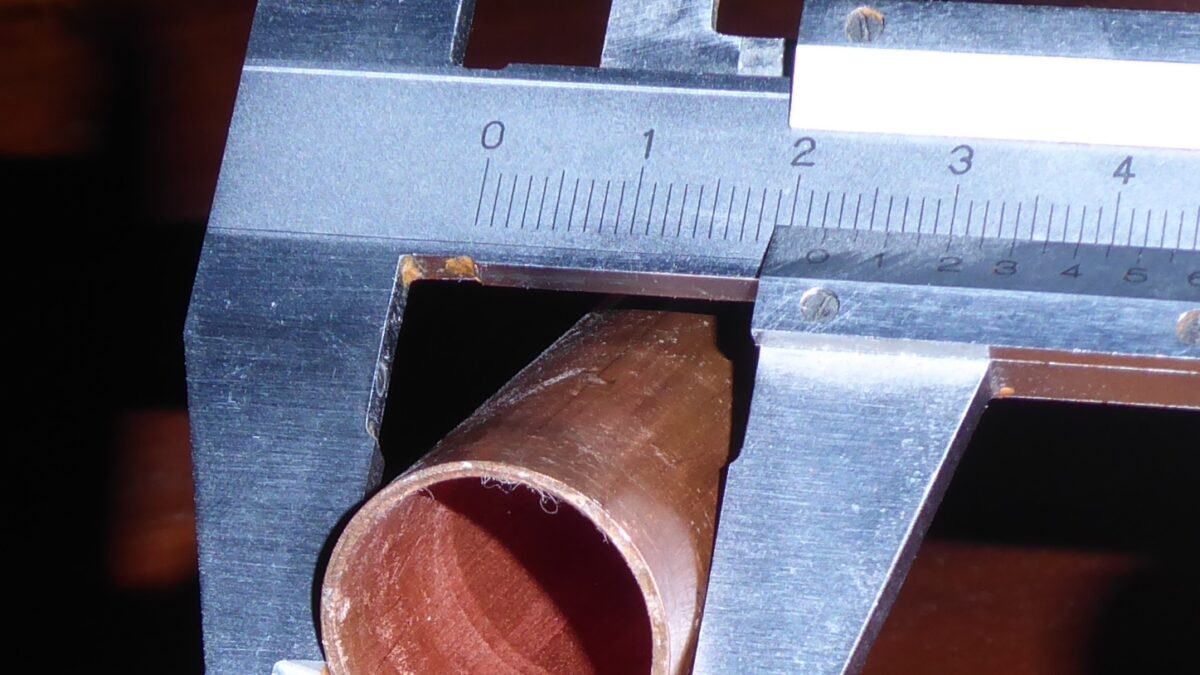
You don’t need special gauges for garage work. A decent pair of dial or digital calipers does the job. Here’s a simple routine that gives repeatable numbers.
- Check your calipers. Close the jaws, wipe them clean, and zero them.
- Measure the straight tube first. Take the max and min OD on a straight section. That’s your starting ovality. Tube isn’t perfectly round from the mill.
- Mark the bend. Find the middle of the bend and mark it with a paint pen. Add marks at the start and end of the bend if you want a fuller picture.
- Measure in the plane of the bend. Place the jaws across the tube from the inside of the bend to the outside. This is usually your Dmin.
- Measure across the bend. Turn the calipers 90° and measure side to side. This is usually your Dmax.
- Hunt for the true max and min. Rock and rotate the calipers a little around the tube at the same spot. Keep the biggest and smallest readings.
- Do the math. Ovality % = (Dmax − Dmin) ÷ Dnominal × 100.
- Write it down. Record the spot, both readings, the result and the setup.
Tips for good readings
Keep the jaws square to the tube’s axis. On a bend, the axis curves, so it’s easy to tilt the calipers and read long. Use light, even pressure. Squeezing hard can flex thin wall and give you a false low reading.
Make sure the jaws are long enough to reach past the tube’s widest point. If they only catch the edges, you’ll read short. On big tube, a larger caliper or a pair of outside calipers and a ruler may be easier.
Finally, measure more than one spot. Ovality isn’t always worst at the exact middle. Taking readings at the start, middle and end of the bend shows you where your setup is struggling.
If the straight tube already measures a little out of round, note it. It helps you see how much ovality the bend itself added, which is what your bender setup controls.
A worked example, step by step
Let’s run the numbers on a 1.75″ OD tube. The readings below are made up to show the math. They aren’t a typical or target result.
Step 1: collect the readings at mid-bend.
- Nominal OD: 1.750″
- Largest reading (across the bend): 1.790″
- Smallest reading (inside to outside of the bend): 1.700″
Step 2: find the difference. 1.790 − 1.700 = 0.090″.
Step 3: divide by the nominal OD. 0.090 ÷ 1.750 = 0.0514.
Step 4: turn it into a percentage. 0.0514 × 100 = about 5.1% ovality.
Now try the alternate version that divides by the sum of the readings. 1.790 + 1.700 = 3.490. Then 0.090 ÷ 3.490 = 0.0258, or about 2.6%. Same tube, same calipers, half the number. That’s why the formula matters.
Turn a limit into a caliper number
It’s often easier to work backwards. Take the allowed percentage, multiply by the nominal OD, and divide by 100. That gives the biggest allowed gap between Dmax and Dmin.
| Limit (nominal formula) | Math on 1.750″ tube | Max allowed Dmax − Dmin |
|---|---|---|
| 1.5% | 1.5 × 1.750 ÷ 100 | About 0.026″ |
| 3% | 3 × 1.750 ÷ 100 | About 0.053″ |
| 5% | 5 × 1.750 ÷ 100 | About 0.088″ |
| 8% | 8 × 1.750 ÷ 100 | 0.140″ |
These percentages are just examples to show the math. Your limit comes from your spec. But notice how our made-up 0.090″ gap would pass an 8% limit and narrowly miss a 5% one. Writing the allowed gap on your bench sheet means you can check parts without a calculator.
Ovality is just two caliper readings and one division. The hard part isn’t the math. It’s knowing whose limit you’re working to.
What’s an acceptable ovality limit?
This is the question everyone asks, and the honest answer is: it depends on who’s setting the rules. We couldn’t find a universal ovality limit for bent tube, and we don’t think one exists. Different jobs need different limits.
Tolerances vary widely from one job to the next, which is why no single number fits every job. A precision hydraulic line and a garden gate have very different needs, so always work to the limit your drawing, customer or rulebook gives you.
Who sets the limit?
- The drawing or customer spec. On contract work, the drawing or purchase order is the boss. If it lists an ovality limit, that’s your number.
- A code or standard. Pressure piping and some industries work to codes that set bend quality rules. If your work falls under one, read the current edition.
- A rulebook. For cages and chassis, your sanctioning body’s current rulebook decides tube, wall and bend rules. SCCA Time Trials, for example, sets a minimum bend radius of three times the tube diameter at the centerline (SCCA Time Trials). Read your own rulebook for anything it says about bend quality.
- The bender or die maker. Some makers publish what their tooling achieves. That’s a capability, not a limit, but it helps you plan.
What if nobody gives you a number?
For your own projects, decide what matters. Does the part need to fit a clamp? Does it carry load? Is it for looks? Then measure your first parts and set a sensible house limit for that job. Write it down so you’re consistent.
Benders Hub is not a tech inspector or an engineer. For roll cages, roll bars and chassis, confirm tube, wall, radius and any bend-quality rules with your current rulebook and your inspector before you buy tube. See our safety notes.
How to reduce ovality in tube bending
The good news is that most ovality problems have simple causes. Fix the cause and the tube stays rounder.
Use a matched die
The die groove should fit your tube’s real OD. A snug groove supports the sides of the tube as it bends. Measure your tube with calipers and buy dies for that size. Don’t put tube in a pipe die or the other way round.
Choose a gentler radius
A bigger CLR means less stretch and squeeze, so less flattening. Baileigh suggests starting around 4 × OD. For 1.75″ tube, that’s a 7″ CLR. Popular off-road dies run a little tighter. Baileigh says 1.75″ dies at about a 6.5″ CLR are common, which is about 3.7D. Check your design and rulebook either way.
Use more wall, or more support
Thicker wall holds its shape better. If you’re bending thin wall on a tight radius, you may need inside support. That means a mandrel. In one example from The Fabricator’s mandrel guide, 2″ × .065″ tube on a 4″ CLR works out to a wall factor of about 30.8 and a D of bend of 2.0. The chart calls for a two-ball mandrel with a wiper.
Add outside support
Some benders offer extra support on the outside of the bend. Rogue Fabrication says its thin-wall roller cuts deformation to about 5–7%, versus about 10% without it (Rogue Fab capacity chart). That’s one maker’s figure for its own tooling, but it shows how much support matters.
| Cause | Fix | Cost |
|---|---|---|
| Ram “pipe bender” | Switch to rotary draw for tube | A new bender |
| Loose die groove | Die matched to real OD | One die |
| Tight CLR | Larger CLR die | One die |
| Thin wall | Thicker wall, if the design allows | Heavier tube |
| Thin wall on tight radius | Mandrel bending or bought mandrel bends | A bigger investment |
As an Amazon Associate I earn from qualifying purchases.
Woodward Fab WFB2: a simple step up from a ram bender
Woodward Fab WFB2 Manual Tube & Pipe Bender
A manual rotary-draw frame that supports tube in a matched die, for round and square tube up to 2″.
If you’re fighting flattened bends on a bottle-jack bender, the biggest single fix is usually a rotary-draw bender with a die that fits your tube. The WFB2 is a common, simple way in. The tube is clamped to a round die and drawn around it, with the groove supporting its sides.
Who it’s for: garage builders bending mild-steel bumpers, sliders, racks and frames who want rounder bends than a ram bender gives.
Keep in mind: it’s not a mandrel bender. Thin-wall tube on tight radii, like exhaust, can still flatten. Dies and the stand are sold separately.
- Type
- Manual rotary draw
- Tube size
- Round and square, up to 2″ with the matching die
- Max wall
- Retail listing for the 2″ die: .134″ mild steel
- Bend angle
- Die listings show about 110°–120°
- Sold separately
- Dies and stand
Why we like it
- Matched dies support the tube’s sides
- Round and square dies available
- Simple to learn on
Know before you buy
- No mandrel, so thin wall on tight radii still flattens
- Manual only: thick wall takes muscle
- Dies add to the total cost
Add-ons: 2″ OD × 6″ CLR die · WFB2 stand. Affiliate links. See our disclosure.
For tight, thin-wall work, read mandrel vs crush bending before you buy anything. And if you’re unsure which bender type suits your tube, our bender type comparison lays them out side by side.
Real-life lessons
These are composite stories. The same situations come up again and again in garage-fab forums and build threads.
A builder bends a set of exhaust tubes on a press-style bender and cuts them right at the end of the bend. The slip couplers won’t slide on. A quick check with calipers shows the tube is clearly wider one way than the other near the bend. They switch to bought mandrel bends for the tight sections and keep their own bends for gentle sweeps.
Lesson: leave a straight section at the ends for joints, and measure before you cut.
Someone buys a used bender with a “1-1/2 inch” die and bends 1.5″ tube in it. Every bend comes out flat on the sides. The die was for 1-1/2″ pipe, which measures 1.900″ OD, so the tube had room to spread.
Lesson: match the die to the tube’s real OD, not the size stamped on a pipe die.
A small shop bends parts for a customer whose drawing says to keep ovality under a set percentage. The shop’s numbers pass. The customer’s inspector fails them. It turns out the shop divided by Dmax + Dmin, and the customer divides by the nominal OD.
Lesson: agree on the formula before the first part ships.
Common ovality mistakes (and how to fix them)
Most ovality trouble comes from a short list of habits. Here’s each one with its fix.
❌ Measuring only one direction. One reading looks fine, so you call it good.
✅ Fix: measure at least two directions at the same spot, then rotate to find the true max and min.
❌ Assuming there’s a universal limit. A number from a forum becomes your pass/fail line.
✅ Fix: get the limit from your drawing, customer, code or rulebook. If none exists, set a house limit and write it down.
❌ Mixing formulas. You divide by one thing, your customer divides by another.
✅ Fix: agree the formula up front and put it on your inspection sheet.
❌ Bending tube in a pipe die. The groove is the wrong size and doesn’t support the sides.
✅ Fix: measure your tube and buy dies for its real OD.
❌ Squeezing the calipers. Hard pressure flexes thin wall and changes the reading.
✅ Fix: use light, even pressure and keep the jaws square to the tube.
❌ Using a ram bender for thin-wall tube. The tube flattens or kinks.
✅ Fix: use a rotary-draw bender for tube, and a mandrel or bought mandrel bends for thin wall on tight radii.
Pro tips for rounder bends
These habits help you get consistent, round bends and catch problems early.
- Baseline every batch. Measure the straight tube’s max and min OD when a new batch arrives. You’ll know what’s the tube and what’s the bend.
- Check your first part properly. Measure the start, middle and end of the first bend on a new setup. If it’s good, spot-check later parts at mid-bend.
- Keep the die clean. Grit or weld spatter in the groove marks the tube and can affect how it seats.
- Watch the D of bend. If you’re below about 3 × OD without a mandrel, expect trouble. Use our bend calculator to work out D of bend and wall factor.
- Leave straight ends for joints. Couplers and clamps seat best on straight tube, away from the bend.
- Log ovality with springback. The same log you use for springback can hold your ovality readings. One line per setup.
- Look at the wall too. Ovality and wall thinning both grow on tight bends. If one is high, check the other.
Experienced fabricators often tape a small card to the bender with the tube size, die, allowed Dmax − Dmin gap and formula. Anyone in the shop can check a part in seconds.
Frequently asked questions
What is ovality in tube bending?
It’s how far a bent tube’s cross-section has moved from a perfect circle. The tube usually flattens in the plane of the bend and widens across it. You express it as a percentage of the tube’s nominal OD.
How do you calculate ovality?
Measure the largest and smallest outside diameters at one spot. Subtract, divide by the nominal OD, and multiply by 100. For example, 1.790″ and 1.700″ on 1.750″ tube gives about 5.1%.
What is an acceptable ovality percentage?
There’s no universal number. Your drawing, customer, code or rulebook sets it. Precision parts need tight limits; structural or decorative parts can often accept more.
How do I measure ovality without special tools?
Use calipers. Measure the tube inside-to-outside of the bend and then side to side at the same spot. Rotate the calipers to find the true largest and smallest readings.
How can I reduce ovality?
Use a rotary-draw bender with a die matched to your tube’s real OD. Choose a larger CLR, use thicker wall if the design allows, and use mandrel support for thin wall on tight radii.
Is ovality the same as flattening?
Mostly, yes. Flattening usually describes a tube that has clearly squashed in one direction. Ovality is the measured percentage of that out-of-roundness.
Your ovality checklist
Use this list on your next bend. It takes a few minutes and keeps surprises off the inspection sheet.
- I know who sets my ovality limit: drawing, customer, code or rulebook
- I know which formula that limit uses
- I’ve turned the limit into an allowed Dmax − Dmin gap for my tube
- My die matches the tube’s real OD, not a pipe size
- My CLR suits the tube, wall and any rulebook minimum
- I measured the straight tube’s starting ovality
- I measured at the start, middle and end of the first bend
- I rotated the calipers to find the true max and min
- I used light, square caliper pressure
- I logged the readings with the tube, die and date
Ovality sounds technical, but it’s really two caliper readings and a little math. Measure it on your first few bends, and you’ll know exactly how round your setup keeps your tube. ✅
Check your bend before you make it
Work out D of bend and wall factor for your tube and die in seconds. Or compare bender types to find one that keeps your tube round.
Keep reading
Exhaust Bend Radius 1D vs 1.5D vs 2D: Geometry and Fitment
Exhaust bend radius 1D vs 1.5D vs 2D explained: CLR = D × OD worked out for common pipe sizes, the space…
Tube Bending Wrinkles, Kinks and Flattening: Causes and Fixes
Fix tube bending wrinkles, kinks and flattening with symptom-to-cause-to-fix tables, clamp and pressure-die checks, and how to read die maker charts.
Mandrel Bending vs Crush Bending Exhaust: What Really Changes
Mandrel bending vs crush bending exhaust, explained simply: what each does to the pipe, when crush bends are fine, and when mandrel…