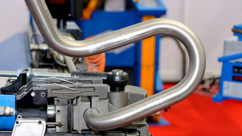
Understanding the Physics Behind Precision Tube Bending
When we bend a tube, we’re actually orchestrating a complex dance of physical forces. Imagine taking a rubber band and bending it – you’ll notice the inside of the bend compresses while the outside stretches. This same principle applies to metal tubing, but with much more critical implications. In technical terms, we’re dealing with plastic deformation under controlled conditions, where the material must stay within specific stress limits to maintain its integrity.
The physics involved follows the fundamental equation σ = E(y/R), where σ represents stress, E is Young’s modulus (a measure of material stiffness), y is the distance from the neutral axis (the centerline of the tube), and R is the radius of curvature. For a typical copper tube with a Young’s modulus of 117 GPa, even a small change in bend radius can significantly impact the stress distribution through the tube wall.
To put this in perspective, when bending a 1/2 inch copper tube with a wall thickness of 0.035 inches, the outer wall experiences tensile stresses approaching 30,000 psi, while the inner wall faces similar compressive forces. Managing these forces precisely is what separates professional-grade bends from amateur attempts.
Tubing Bender Pipe Bender Hvac tools
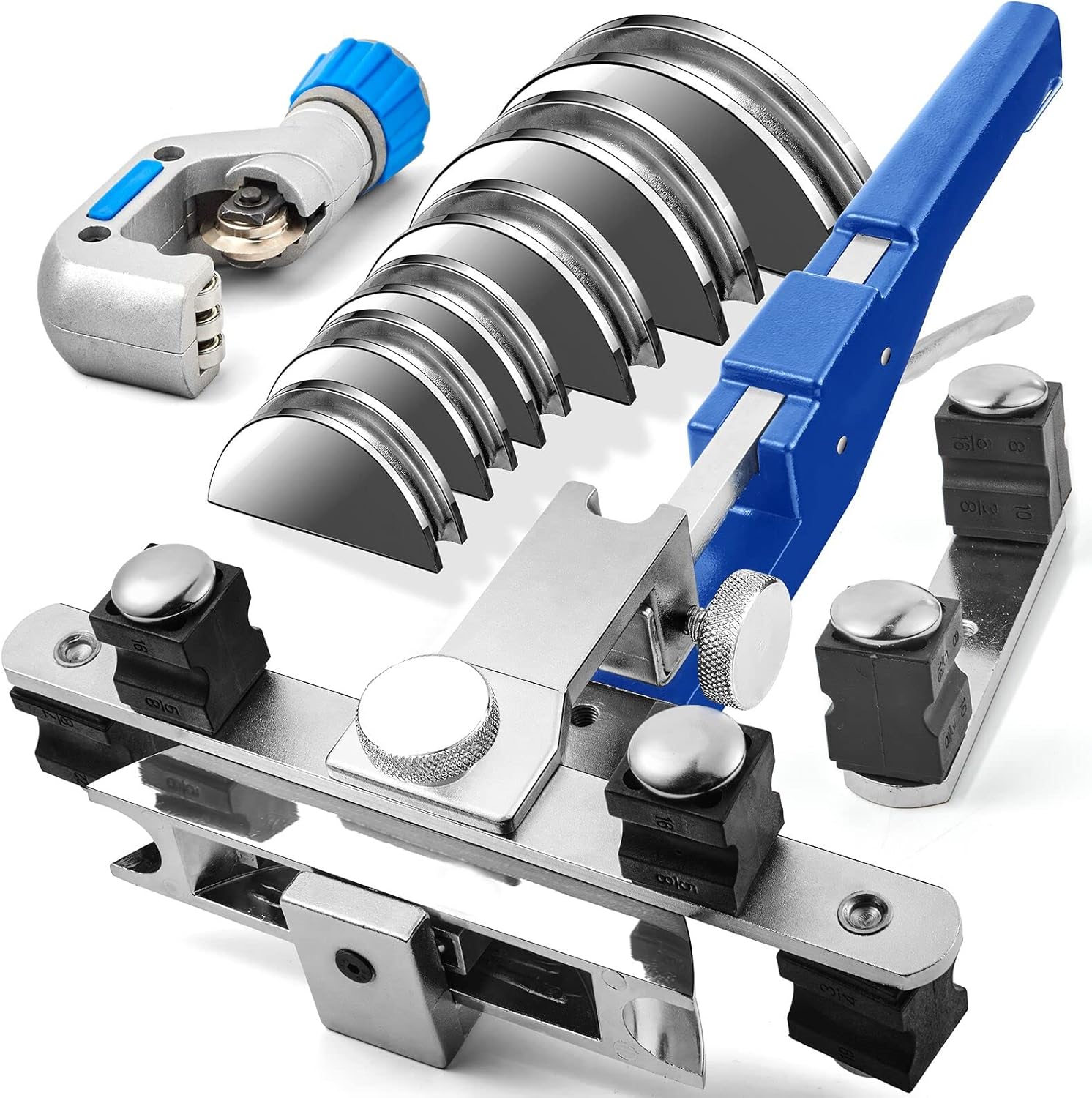
- We provides THREE-YEAR FACTORY WARRANTY. Suitable Tube Size: 1/4“, 5/16“, 3/8“, 1/2”, 5/8“, 3/4“, 7/8”, the maximum bending angle of elbow pipes 90 degrees, support reverse bend. bending pipes in both “forward” and “reverse” configurations.
- Made of 40CR steel and 45# steel. Suitable for bending annealed metal materials or PVC pipes, such as thin-walled steel pipes (thickness<0.05 inch), aluminum pipes (thickness<0.08inch), soft copper (thickness<0.08inch).
Material Science: The Foundation of Superior Performance
Advanced Steel Metallurgy
The Tubing Bender Kit’s framework utilizes 40CR steel (AISI 5140), a material choice that reflects deep understanding of metallurgical principles. Let’s explore why each element matters:
Carbon (0.38-0.43%): This precise carbon range is crucial. Too little carbon (below 0.35%) would make the steel too soft for precision tools, while too much (above 0.45%) would create brittleness. Think of carbon atoms as tiny reinforcing particles within the steel’s crystal structure, much like rebar in concrete. During heat treatment, these carbon atoms position themselves between iron atoms, creating a structure called martensite, which provides the optimal balance of strength and toughness.
Chromium (0.80-1.10%): Chromium serves multiple purposes. First, it forms hard carbide particles that enhance wear resistance – imagine these as microscopic armor plates distributed throughout the steel. Second, chromium provides corrosion resistance by forming a thin, invisible oxide layer on the surface, similar to how a coat of wax protects a car’s paint.
The heat treatment process is equally sophisticated:
- Austenitization at 850°C: At this temperature, the steel’s crystal structure transforms to allow carbon atoms to move freely, like shuffling cards in a deck.
- Oil Quenching: Rapid cooling freezes the carbon atoms in position, creating the strong martensite structure. The oil medium provides a cooling rate of approximately 200°C per second, fast enough to achieve desired hardness but not so fast as to cause cracking.
- Tempering at 420°C: This final step relieves internal stresses while maintaining hardness. It’s like allowing a freshly baked loaf of bread to cool gradually – too fast and it might crack, too slow and it won’t achieve the right texture.
Revolutionary Ratcheting Mechanism
The ratcheting mechanism represents a masterpiece of mechanical engineering. It employs 45# steel processed to exacting specifications:
Surface Hardness: The mechanism achieves 58-62 HRC (Rockwell C scale) hardness through induction heating. This process creates a case depth of 0.5-0.7mm, providing a hard outer shell while maintaining a tougher core. Imagine a candy with a hard shell and chewy center – the outer layer resists wear while the inner core prevents brittle failure.
Engagement Geometry: The pawl system uses a 27.5° engagement angle with a precisely calculated tooth profile. This specific angle results from extensive engineering calculations balancing several factors:
- Force transmission efficiency (maximum at 14.5°)
- Self-locking capability (requires >18°)
- Wear resistance considerations
- Manufacturing tolerances
The tooth profile follows an involute curve, the same geometry used in high-performance gear systems. This shape ensures smooth engagement and disengagement while maximizing load distribution across the tooth surface. The root fillet radius of 0.38mm represents an optimal compromise between stress concentration reduction and tooth strength.
Die Set Engineering: Where Theory Meets Practice
DURATECH Tube Bender Set
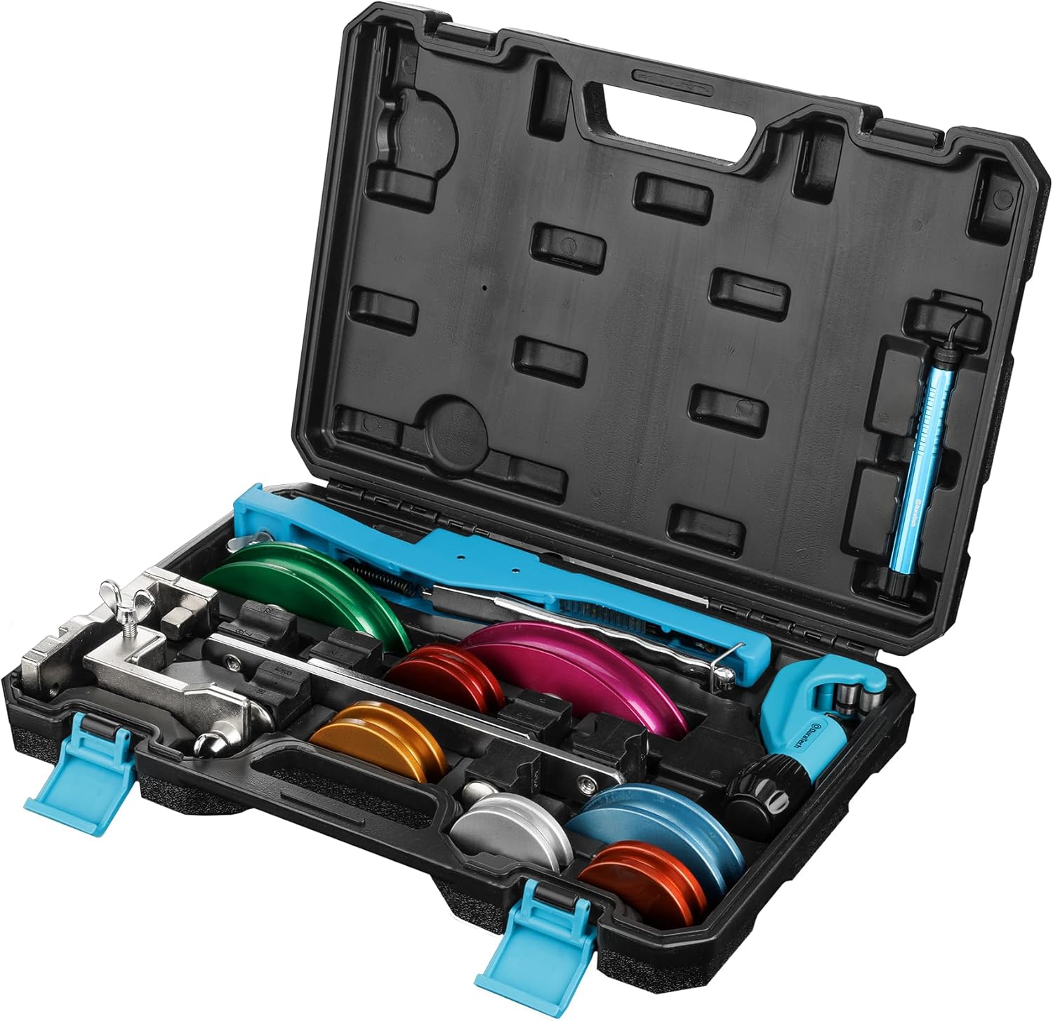
Tube Bender x 1, Tube Bender Heads x 7 (size ranging 1/4 ”, 5/16 ”, 3/8 ”, 1/2 ”, 5/8 ”, 3/4 ”, 7/8 ”), Crossbars x 2 (applicable for pipe outer diameter 1/4 ” to 7/8 “), Reverse Bender Adapters x 2, Tube Cutter x 1, Deburring Tool x 1. A hard plastic storage box for easy organization and portability The bender is constructed from high-quality aluminum alloy, providing extra strength and sufficient bending force while being lightweight for easy operation.
The die sets exemplify the marriage of theoretical engineering and practical application. Each set incorporates sophisticated geometry that goes far beyond simple curves:
Advanced Groove Geometry
The groove profile follows a modified parabolic equation: y = ax² + bx + c + d(x⁴)
Where the fourth-order term d(x⁴) provides additional control over the contact pressure distribution. This seemingly complex formula translates into real-world benefits:
The primary radius (R1) equals 2.5 times the tube diameter, optimizing the balance between bend tightness and material strain. A secondary relief radius (R2), slightly larger at R1 + 0.2mm, prevents tube binding during the bending process. This dual-radius design, combined with a 185° contact arc, ensures complete tube support while allowing necessary material flow during bending.
Surface Engineering: The die surfaces undergo precise finishing to achieve Ra 0.4 μm roughness. To understand this level of smoothness, consider that a human hair is about 100 μm in diameter – these surfaces are polished to variations less than 1/250th that size. This extraordinary smoothness prevents surface damage to the tubing while reducing friction during the bending process.
Material Selection and Treatment
The D2 tool steel used in die construction contains carefully balanced alloying elements:
- Carbon (1.40-1.60%): For wear resistance
- Chromium (11.0-13.0%): For corrosion protection
- Molybdenum (0.70-1.20%): For high-temperature strength
- Vanadium (0.70-1.20%): For grain refinement and enhanced toughness
The heat treatment process involves multiple stages:
- Preheating to 815°C to prevent thermal shock
- Austenitizing at 1025°C for complete carbide dissolution
- Air quenching to minimize distortion
- Triple tempering at 205°C for dimensional stability
- Deep cryogenic treatment at -185°C for maximum wear resistance
This complex treatment sequence results in a microstructure optimized for both wear resistance and toughness. The final product exhibits carbide particles approximately 5-10 μm in size, uniformly distributed throughout the matrix for maximum wear resistance.
Performance Optimization and System Integration
The complete system demonstrates remarkable precision through careful integration of all components:
Bend Accuracy: The system achieves ±0.5° angular tolerance through several mechanisms:
- Precise pawl engagement spacing (72 positions per 360°)
- Rigid frame construction with less than 0.1mm deflection under maximum load
- Temperature-compensated design maintaining accuracy across 10-40°C operating range
Wall Thickness Variation: Maintained within 5% through:
- Optimized die groove geometry
- Controlled material flow during bending
- Precise pressure application through the ratcheting mechanism
The system’s practical capabilities are equally impressive:
- Maximum bend angle: 180° (complete U-bends)
- Minimum straight section: 2× tube diameter
- Repeatability: ±0.2° between successive bends
Conclusion
The Tubing Bender Kit represents the culmination of advanced engineering principles applied to practical problems. Understanding its technical sophistication – from the metallurgical foundations to the precision mechanical systems – helps users appreciate why proper tool selection and usage matter so much in achieving professional results. Just as a master chef relies on quality knives and understanding of cooking science, professional-grade tube bending requires both excellent tools and comprehensive knowledge of the underlying principles.
Read More From Us
- The IDEAL 74-057 Guardian Conduit Bender: Your Precision Ally for Electrical Work
- The 12 Ton Hydraulic Pipe Bender: A Comprehensive Guide to Features, Usage, and Benefits
- Advanced Buying Guide for Benders
- Kraft Tool Co. CC029 Walking Seamer-Groover: Your Precision Partner for Flawless Concrete Finishes
- Mastering Pipe Bends with the Teodute Pipe Tube Bender: An In-Depth Review